Land Rover Discovery. Manual - part 169


  Index      Land Rover     Land Rover Discovery - service 1995-1996 year


Search            


Content   ..  167  168  169  170   ..


Land Rover Discovery. Manual - part 169


76

CHASSIS AND BODY

8

REPAIR

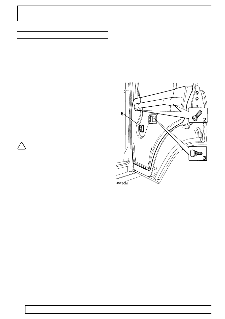
REAR SIDE DOOR - TRIM PANEL

Service repair no - 76.34.04

Remove

1. Disconnect battery negative lead.
2. Remove the two securing screws and detach the

door pull from its mounting brackets.

3. Remove the securing screw and detach the

interior door release handle surround.

4. Where applicable remove the window winder or

release electric switch and disconnect.

5. Detach the trim panel by inserting a trim panel

removing tool between the trim panel and the
inner door panel, gently prise out the plastic
securing clips from their respective holes in the
inner panel.

6. Lift the trim panel over the remote button and

clear of the door. Where applicable disconnect
the electrical plug from the window lift switch and
withdraw the panel.

NOTE: With the trim panel removed the
remote button and rod will fall from its
location in the bellcrank. Observe its

correct location and withdraw from the door
panel.

7. If a new trim panel is to be fitted, remove the

window lift switch, door bin and remote button
finisher from the existing trim panel and fit them
to the new panel.

Refit

8. Reverse removal procedure. Ensuring correct

fitment of the sill button operating rod.

CHASSIS AND BODY

9

REPAIR

REAR SIDE DOOR LOCK, INSIDE AND OUTSIDE
RELEASE HANDLES

Service repair no - 76.37.13/32

Remove

1. Ensure that the window is in the fully closed

position.

2. Disconnect battery negative lead.
3. Remove the interior trim panel from the door.

See rear side door - trim panel.

4. Remove the plastic vapour barrier sheet.
5. Disconnect the inside release handle control rod

by pulling it from its location in the door lock.

6. Disconnect the sill locking control rod from the

lock by releasing the metal clip.

7. Disconnect the outside release handle control

rod by pulling it out of the plastic ferrule.

8. Remove the two countersunk screws from the

door edge and the single screw and shakeproof
washer from the inner door panel. Retrieve any
spacing washers which may be fitted between
the inner door panel and lock.

9. Withdraw the lock through the upper rear

opening in the inner door panel.

NOTE: If necessary the following items
can be removed.

10. Remove the two nuts, shakeproof washers and

retaining bracket securing the outer release
handle which are accessible through the upper
rear cut-out on the inner door panel.

11. Carefully detach the handle from the outer door

panel.

12. Remove the two screws and plain washers

securing the inside release handle to the inner
door panel and withdraw the handle complete
with connecting rod.

13. Disconnect the sill button connecting rod from

the bellcrank and withdraw the rod complete with
sill button.

Sill locking bellcrank

14. Using a small screwdriver, or length of 3.175 mm

(1/8 in) diameter rod, press the plastic locking
pins through the respective square inserts in the
inner door panel.

15. Release the bellcranks from the inner door panel

and unhook the respective connecting rods.

16. Withdraw the bellcranks from inside the door

panels.

NOTE: When refitting the bellcranks the
locking pins are entered into the square
insert from outside and pressed in flush.

76

CHASSIS AND BODY

10

REPAIR

ADJUSTMENT-REAR SIDE DOOR LOCK AND
HANDLE

Service repair no - 76.37.47

Outside door release handle to lock

1. Disconnect the short off-set connecting rod at

the rear of the outer release handle, rotate the
rod clockwise or counter clockwise to shorten or
extend the operating length of the rod as
required.

NOTE: Door release should occur before
the total handle movement is achieved to
provide a small overthrow movement.

REAR SIDE DOOR GLASS AND REGULATOR

Service repair no - 76.31.45

Remove

1. Ensure that the window is in the fully closed

position and secure it with adhesive tape over
the top of the door to prevent the glass from
dropping down.

2. Disconnect battery negative lead.
3. Remove the door trim panel.

See rear side

door - trim panel.

4. Remove the plastic vapour barrier.
5. Where applicable remove the door actuator and

window lift motor.

See ELECTRICAL, Repair,

window lift motor - rear. See ELECTRICAL,
Repair, rear side door actuator units.

6. Remove the four window regulator securing

screws and shakeproof washers from the inner
door panel.

7. Carefully disengage the lifting arm stud from the

glass lifting channel and remove the window
regulator from the lower opening in the inner
door panel.

8. Remove the waist rail seal from the top of the

door panel.

9. Remove the single bolt, spring and plain

washers from inside the door, securing the
bottom of the short glass run channel.

10. Remove the two bolts, spring and plain washers

from the hinge face of the door.

CHASSIS AND BODY

11

REPAIR

11. Remove the two bolts, spring and plain washers

securing the door frame to the edge of the door.

12. Lift out the door frame complete with glass and

remove to a suitable workbench.

13. Remove the tape and slide the glass out of the

door frame channel.

Refit

14. Reverse removal procedure.

NOTE: When refitting the door glass frame
ensure that it is adjusted to suit the door
opening before fully tightening the

securing bolts.

REAR DOOR

Service repair no - 76.28.19

Remove

1. Remove the spare wheel from the exterior of the

door.

2. Remove the trim panel from inside the rear door.

See rear door trim panel.

3. Release the convoluted grommet from the door

post, expose the door harness connectors and
multiplugs and disconnect.

4. Remove the circlip and washer from the check

stay pivot on the body.

WARNING: Instruction 5 MUST BE carried
out with assistance.

5. Suitably support the door, remove the four bolts

securing the hinges to the door and with
assistance slide the door off the hinges.

Refit

6. Reverse removal procedure.


Content   ..  167  168  169  170   ..