Land Rover Discovery. Manual - part 166
75
SUPPLEMENTARY RESTRAINT SYSTEM
18
REPAIR
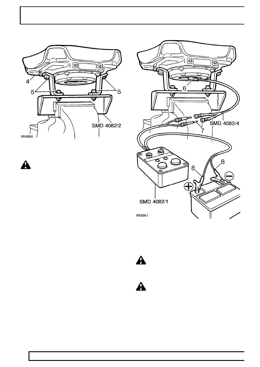
WARNING: Ensure tool SMD 4082/1 is not
connected to battery.
4. Secure airbag module to tool SMD 4082/2.
Ensure module is correctly secured using both
fixings.
5. Ensure airbag module mounting brackets are
secure.
6. Connect flylead SMD 4082/4 to airbag module.
7. Connect flylead SMD 4082/4 to tool SMD
4082/1.
WARNING: Do not lean over module whilst
connecting.
8. Connect tool SMD 4082/1 to battery.
WARNING: Ensure all personnel are
standing at least 15 metres (50 ft) away
from module.