Land Rover Discovery. Manual - part 164


  Index      Land Rover     Land Rover Discovery - service 1995-1996 year


Search            


Content   ..  162  163  164  165   ..


Land Rover Discovery. Manual - part 164


75

SUPPLEMENTARY RESTRAINT SYSTEM

10

REPAIR

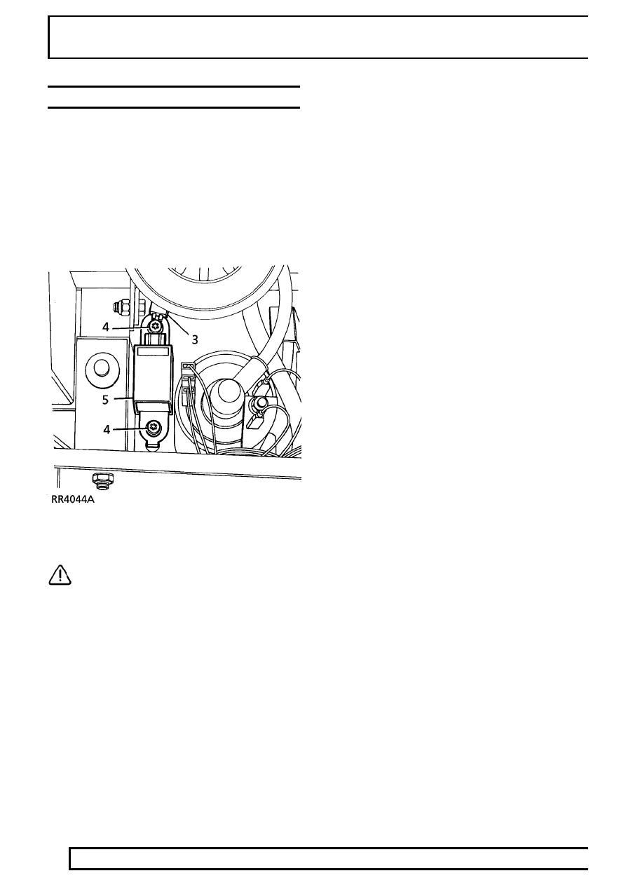
CRASH SENSOR - DISTRIBUTED SRS

Service repair no - 76.74.04

Remove

1. Disconnect battery negative lead.
2. LH sensor only: Slacken power steering

reservoir clamp and lift reservoir to provide
access.
Diesel model only: Remove jack and mounting
bracket.

3. Disconnect multiplug from sensor

CAUTION: Ensure airbag harness
connector seal and anti-backout DO NOT
come adrift when disconnecting sensor.

4. Use special socket, remove 2 screws securing

crash sensor to body.

5. Remove crash sensor.

Refit

6. Reverse removal procedure.
7. Tighten crash sensor securing screws to

10 Nm

(7 lbf ft). Ensure multiplug is fully engaged on
sensor and retained by its latch.

8. Check Supplementary Restraint System using

Testbook.

SUPPLEMENTARY RESTRAINT SYSTEM

11

REPAIR

AIRBAG DIAGNOSTIC CONTROL UNIT -
DISTRIBUTED SRS

Service repair no - 76.74.03

Remove

1. Disconnect battery negative lead.
2. Remove centre console assembly.

See

CHASSIS AND BODY, Repair, centre
console.

3. Remove 4 screws and release the 2 rear

passenger air ducts from their fitted position and
remove centre console mounting bracket.

4. Use flat ended screwdriver and release

YELLOW retainer, pull retainer 30mm (1 1/8 in)
from multiplug and disconnect airbag harness
multiplug from airbag control unit.

5. Use special socket, remove 2 screws securing

airbag control unit to body bracket.

6. Remove airbag diagnostic control unit.

Refit

7. Reverse removal procedure.
8. Tighten control unit securing screws to

10Nm (7

lbf ft).

9. Check Supplementary Restraint System using

Testbook.

75

SUPPLEMENTARY RESTRAINT SYSTEM

12

REPAIR

SRS WARNING LIGHT BULBS

Service repair no - 76.73.74

Remove

1. Remove instrument binnacle.

See

ELECTRICAL, Repair, instrument binnacle.

2. Remove window and face plate from instrument

panel.

3. Remove 3 screws securing ECU to instrument

panel.

4. Release and remove small cover from ECU.
5. Disconnect multiplug from ECU.
6. Remove ECU

7. Remove 4 screws securing tachometer.
8. Remove tachometer.

SUPPLEMENTARY RESTRAINT SYSTEM

13

REPAIR

9. Carefully remove 2 screws securing face plate to

tachometer.

10. Release warning light housing from tachometer

circuit board.

11. Carefully (to avoid damage to tachometer needle

and spindle), tilt and remove warning light
housing.

12. Remove 2 warning light bulbs.

Refit

13. Reverse removal procedure.
14. Fit new warning light bulbs.
15. Carefully fit warning light housing, ensuring that

locating pegs engage correctly and that retaining
clips lock housing into position.

16. Ensure that tachometer needle is on the correct

side of its stop.

17. Fit instrument binnacle.

See ELECTRICAL,

Repair, instrument binnacle.


Content   ..  162  163  164  165   ..