Defender 300Tdi (1996+). Manual - part 97


  Index      Land Rover     Defender 300Tdi - service repair manual 1996 year


Search            


Content   ..  95  96  97  98   ..


Defender 300Tdi (1996+). Manual - part 97


AIR CONDITIONING

11

REPAIR

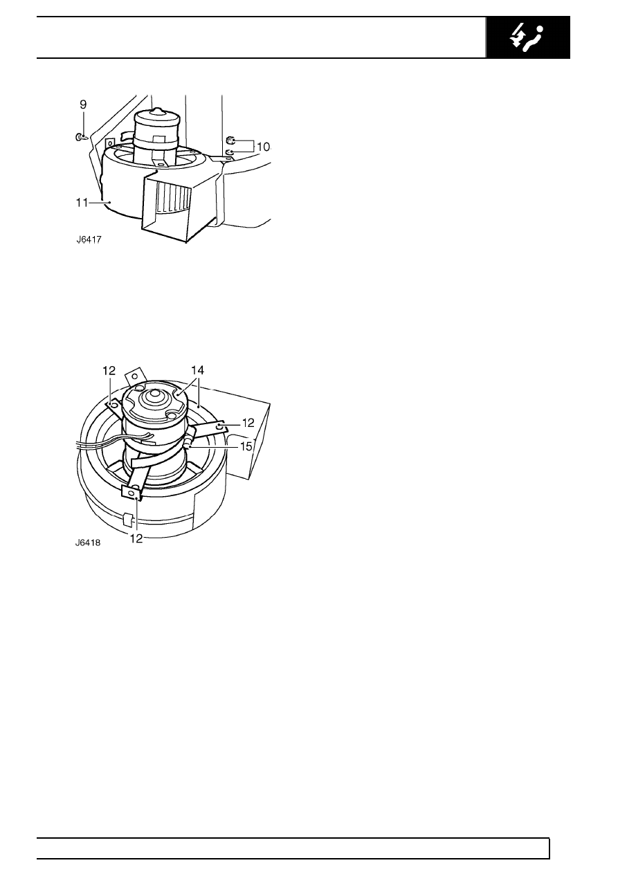
9. Remove screw securing blower motor mounting

bracket to side of casing.

10. Remove nut and washer securing blower motor

housing to pedestal mounting bracket.

11. Lift blower motor assembly from casing.

12. Remove 3 screws and withdraw blower motor

and impellor from housing. Note position of side
mounting bracket and spacing washers between
motor mounting and housing.

13. Remove star washer and withdraw impeller from

blower motor.

14. Lift motor from plastic mounting.
15. Slacken retaining clip and remove 3 support

brackets.

Refit

16. Secure support brackets to new blower motor.

Do not fully tighten clip at this stage.

17. Insert motor into plastic mounting and fit

impeller.

18. Locate spacing washers, side mounting bracket,

and fit motor and mounting into motor housing.

19. Secure assembly to motor housing and fully

tighten support bracket retaining clip.

20. Fit blower motor assembly in main casing.
21. Apply sealing compound around top edge of

main casing.

22. Feed blower motor wiring through top cover and

fit grommet.

23. Fit top cover to casing. Ensure thermostat

temperature probe is inserted in top of
evaporator. Apply mastic sealant to air flap
operating rod aperture.

24. Apply sealing compound to joint face of blower

motor outlet duct.

25. Locate duct over blower motor outlet and secure

to casing.

26. Fit heater/cooler unit

See Heater/cooler unit.

82

AIR CONDITIONING

12

REPAIR

BLOWER MOTOR ASSEMBLY - RH DRIVE

Service repair no - 82.25.14

Remove

1. Disconnect blower motor wiring plugs.
2. Remove 2 screws securing blower motor cover

to main casing.

3. Withdraw cover sufficiently to release motor

Lucar connector and earth eylet. Remove cover.

4. Remove 6 screws and withdraw blower motor

and impeller.

5. Remove retaining nut and washer and withdraw

impeller from blower motor shaft.

Refit

6. Secure impeller on new blower motor.
7. Fit blower motor assembly in main casing.
8. Fit Lucar connector and earth eyelet to blower

motor.

9. Fit blower motor cover and connect wiring plugs.

AIR CONDITIONING

13

REPAIR

HEATER/COOLER UNIT - RH DRIVE

Service repair no - 82.25.21

Remove

1. Disconnect battery.
2. Recover refrigerant from air conditioning system

See Refrigerant recovery, recycling,
recharging.

3. Release ties, remove insulation cover and

disconnect evaporator low pressure pipe.

4. Disconnect evaporator high pressure pipe.
5. Discard all pipe connection ’O’ rings. Cap or plug

all connections to prevent ingress of dirt and
moisture.

6. Using suitable pipe clamps, clamp heater matrix

feed and return pipes at heater/cooler unit.

7. Remove screw securing air control flap solenoid.
8. Disconnect 2 leads from thermostat.
9. Remove pipe from water valve vacuum switch.

10. Remove retaining clip and disconnect control

cable from evaporator flap operating rod.

11. Remove screw and release outer cable retaining

bracket.

12. Disconnect blower motor wiring plugs and

release harness retaining clip from housing.

13. Remove bolt securing front support bracket to

blower motor housing. If necessary, remove
blower motor resistor block to facilitate
operation.

14. From inside vehicle remove front passenger

carpet, if fitted.

15. Remove fixing screws and fold back footwell

insulation.

16. Remove 4 bolts securing heater/cooler unit lower

mounting bracket to bulkhead. Ensure spacing
washers from two innermost bolts are retrieved
from engine bulkhead side.

17. From inside engine compartment remove 2 bolts

securing top heater/cooler unit mounting bracket
to engine bullkhead.

18. Lift heater/cooler unit clear of air duct seal and

remove from vehicle.

82

AIR CONDITIONING

14

REPAIR

Refit

19. Coat unions, threads and new ’O’ rings with

refrigerant oil prior to reassembly.

20. Position heater/cooler unit in engine

compartment and locate with air duct seal.

21. Secure unit top and bottom mounting brackets to

bulkhead and support bracket to front of unit
casing. Fully tighten fixing bolts when unit is
correctly positioned.

22. If applicable, fit blower motor resistor block to

vehicle wing.

23. Connect blower motor wiring plugs.
24. Fit footwell insulation and carpet.
25. Fit control cable to evaporator flap operating rod

using new clip. Secure outer cable.

26. Connect water valve vacuum switch pipe and

thermostat leads.

27. Fit air control flap solenoid to side of

heater/cooler unit.

28. Reconnect heater matrix hoses.
29. Connect high pressure pipe to evaporator.
30. Connect low pressure pipe and fit insulation

cover.

31. Evacuate and recharge air conditioning system

See Adjustment, Refrigerant recovery,
recycling, recharging.

32. Reconnect battery.


Content   ..  95  96  97  98   ..