Defender 300Tdi (1996+). Manual - part 39


  Index      Land Rover     Defender 300Tdi - service repair manual 1996 year


Search            


Content   ..  37  38  39  40   ..


Defender 300Tdi (1996+). Manual - part 39


MANUAL GEARBOX

1

REPAIR

R380 GEARBOX

Service repair no - 37.20.51
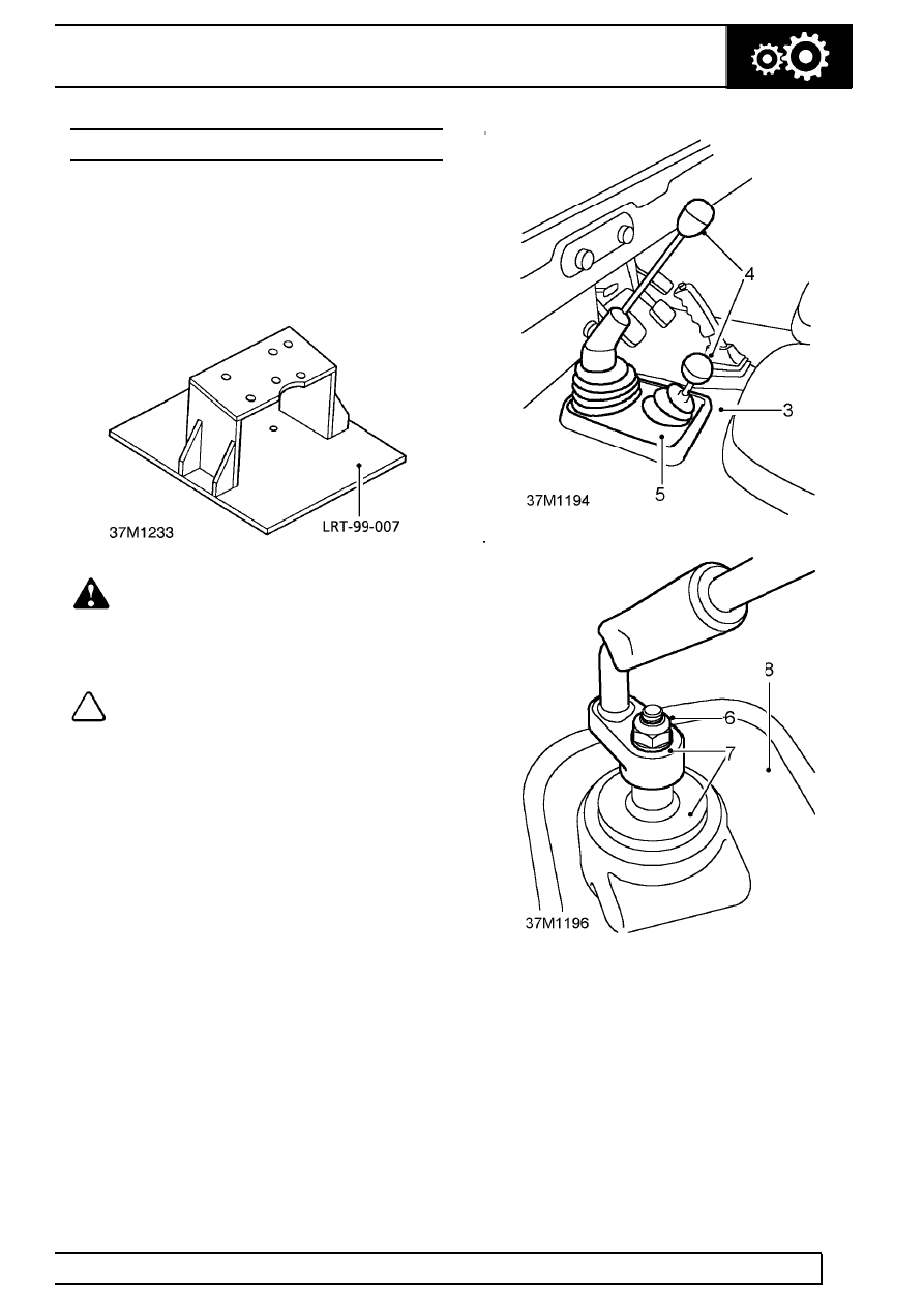
Remove

The R380 gearbox should be removed from
underneath the vehicle, using a hydraulic hoist and
support plate LRT-99-007.

WARNING: Where the use of a
transmission hoist is necessary, it is
absolutely essential to follow the

manufacturer’s instructions to ensure safe and
effective use of equipment.

NOTE: A chassis undertray may be fitted
on some vehicle derivatives to conform to
legal requirements. When under chassis

remove and refit procedures are required, it may
be necessary to remove the undertray

See

CHASSIS AND BODY, Repair, Front undertray or
See CHASSIS AND BODY, Repair, Rear undertray
.

1. Install vehicle on a ramp.
2. Disconnect battery.
3. Remove gearbox carpet.
4. Remove gear lever and transfer box lever knobs.
5. Remove gear lever cover.
6. Remove nut and washer securing gear lever.
7. Mark gear lever spline setting and remove lever

and gaiter from the splined lower gear lever.

8. Release insulation pad from tunnel cover and

gear levers and remove.

9. Select low range on transfer box lever to prevent

lever from fouling tunnel when removing gearbox

37

MANUAL GEARBOX

2

REPAIR

10. Remove 3 trim studs and lift up handbrake

gaiter.

11. Remove split pin, clevis pin, washer and

disconnect cable from handbrake lever. Ensure
handbrake is off.

12. Drain cooling system

See COOLING SYSTEM,

Adjustment, Drain and refill cooling system .

13. Remove viscous fan unit

See COOLING

SYSTEM, Repair, Viscous coupling and fan .

14. Slacken retaining clip and disconnect radiator

top hose at thermostat housing.

15. Slacken retaining clip and disconnect intake

hose at induction manifold. If EGR system is
fitted, slacken 2 retaining clips and disconnect
intake hose at intercooler.

16. Slacken retaining clip and disconnect hose at

turbocharger.

17. Remove bolt securing transmission breather

pipe clip to rear of engine.

18. Release breather pipes.
19. Release ties securing gearbox harness to

breather pipes.

20. Raise vehicle on ramp.
21. Position a suitable container under transmission

and drain main gearbox and transfer box

See

SECTION 10, Maintenance, Under vehicle
maintenance 
.

22. Mark front propeller shaft drive flange and

transfer box output flange for reassembly.

23. Remove 4 nuts and disconnect propeller shaft

from transfer box.

MANUAL GEARBOX

3

REPAIR

24. Remove 2 bolts, withdraw clutch slave cylinder

and backing plate from bell housing, and tie
aside.

25. Mark rear propeller shaft drive flange and

transmission brake drum for reassembly.

26. Remove 4 nuts, disconnect propeller shaft from

brake drum, and tie aside.

27. Remove front pipe from exhaust manifold

See

MANIFOLD AND EXHAUST SYSTEM, Repair,
Exhaust front pipe 
.

28. Remove intermediate silencer.

See MANIFOLD

AND EXHAUST SYSTEM, Repair,
Intermediate pipe - 90 
or See MANIFOLD
AND EXHAUST SYSTEM, Repair,
Intermediate pipe - 110/130

29. Temporarily support transmission.
30. Remove nut securing gearbox LH mounting

rubber to chassis crossmember.

31. Remove 4 nuts and bolts securing crossmember

to chassis longitudinals.

32. Remove nut securing transfer box mounting

rubber to RH side of crossmember.

33. Remove 4 nuts and bolts securing crossmember

to chassis longitudinals.

34. With assistance and using a body jack between

chassis longitudinals, jack chassis sufficiently to
enable removal of crossmember.

35. Remove chasss crossmember.
36. Remove 4 bolts from both sides and remove LH

and RH mounting brackets.

37

MANUAL GEARBOX

4

REPAIR

37. Pull handbrake cable through heel board and tie

aside.

38. Remove retaining nut, release clamp, and

disconnect speedometer cable from transfer box.

39. Release speedometer cable from retaining clip

on transfer box.

40. Remove retaining nut and release battery earth

strap from transfer box.

41. Secure manufactured cradle LRT-99-007 to a

suitable hydraulic hoist.

42. Raise hoist and secure to gearbox with 3 bolts in

location provided.

43. Lower hoist sufficiently to allow transfer lever to

clear transmission tunnel aperture.

44. Disconnect differential lock switch and reverse

light connectors.

45. Remove bolt and release earth leads from RH

side of transfer box.

46. Support engine under sump with a jack.
47. Remove 14 bell housing to engine fixings.
48. Withdraw transmission whilst ensuring all

connections to engine and chassis are released.

49. Lower hoist and remove gearbox assembly.


Content   ..  37  38  39  40   ..