Defender 90 NAS. Manual - part 36
TRANSFER GEARBOX
7
REPAIR
SHIFTLOCK SOLENOID
Service repair no - 41.20.63
Remove
1. Remove centre console.
See CHASSIS AND
BODY, Repair, Centre console
2. Remove carpet from transmission tunnel.
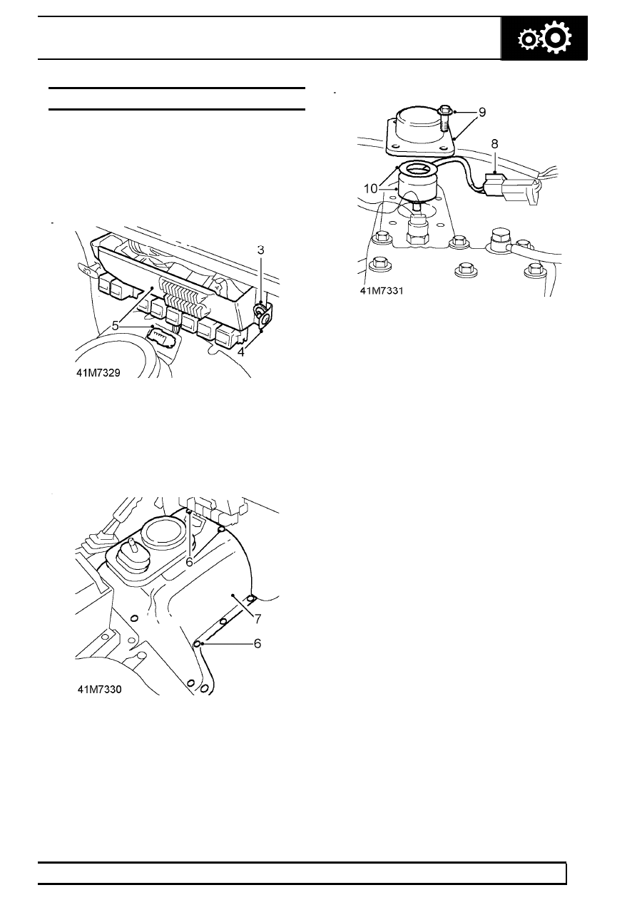
3. Remove 2 screws securing relay panel.
4. Retain 2 centre console screw brackets and
spacers.
5. Release connector J1962 from bracket on tunnel
cover and move relay panel aside to gain access
to tunnel cover top fixings.
6. Remove 15 screws securing tunnel cover.
7. Release and remove tunnel cover.
8. Disconnect shiftlock solenoid multiplug.
9. Remove 4 bolts and release solenoid cover from
transfer box.
10. Remove solenoid and washer.
11. Clean joint sealant from mating faces.
Refit
12. Apply Hylosil or equivalent sealant to mating
faces.
13. Fit solenoid. Ensure solenoid multiplug lead is
located in cover recess.
14. Secure solenoid cover to transfer box. Tighten
bolts to
9 Nm (7 lbf/ft).
15. Connect solenoid multiplug.
16. Fit tunnel cover.
17. Secure connector J1962 to bracket on tunnel
cover.
18. Position centre console screw bracket and
spacers and fit relay panel.
19. Fit tunnel carpet.
20. Fit centre console.
See CHASSIS AND BODY,
Repair, Centre console