Defender 90 NAS. Manual - part 37
44
AUTOMATIC GEARBOX
2
DESCRIPTION AND OPERATION
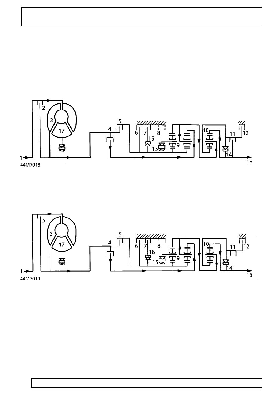
Power flow
1st gear D selected
With D selected 1st gear engaged, clutches 4 and 11 are operative. The front planet gear carrier of gear set 9 is
locked against the housing through freewheel 15 when the engine is pulling but freewheels when the vehicle is
coasting. Epicyclic gear set 10 rotates as a solid unit with the front planet gear carrier. In selector position 1 with
1st gear engaged, clutch 8 operates to prevent the loss of drive on the overrun through freewheel 15, to provide
engine braking.
2nd gear D selected
Clutches 4, 6, 7 and 11 are engaged. Freewheel 15 overruns, the hollow shaft with the sun wheel of epicyclic gear
set 9 is locked. Epicyclic gear set 10 also rotates as a solid unit.