Defender 90 NAS. Manual - part 35


  Index      Land Rover     Defender 90 NAS - service manual 1997 year


Search            


Content   ..  33  34  35  36   ..


Defender 90 NAS. Manual - part 35


TRANSFER GEARBOX

3

REPAIR

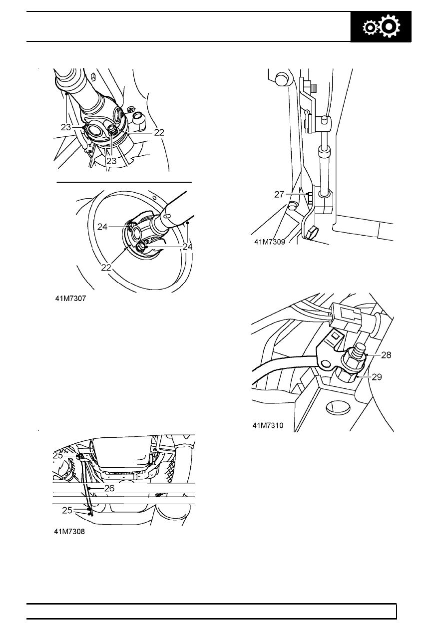
22. Using a centre punch, mark relationship between

front propeller shaft and transfer box drive
flanges and rear propeller shaft and brake drum
drive flanges.

23. Remove 4 nuts securing front propeller shaft to

transfer box flange. Release propeller shaft from
flange and tie aside.

24. Remove 4 nuts securing rear propeller shaft to

brake drum flange. Release propeller shaft from
flange and tie aside.

25. Remove nut securing tie bar to gear box and 2

bolts securing tie bar to transfer box.

26. Remove tie bar.

27. Remove bolt securing selector outer cable clamp

to transfer gearbox LH mounting.

28. Remove nut securing oxygen sensor multiplug

bracket to transfer gearbox earth bolt and collect
bracket.

29. Remove nut securing earth strap to transfer

gearbox and release strap.

41

TRANSFER GEARBOX

4

REPAIR

30. Release handbrake outer cable from body.

31. Remove bolt securing ground lead to RH side of

transfer gearbox.

32. Remove bolt securing handbrake cable heat

shield. Remove heat shield.

33. Position adaptor plate, LRT-99-010, and secure

to transmission hoist with 4 bolts.

34. Remove 4 central bolts from transfer gearbox

bottom cover, move hoist into position and
secure adaptor plate to transfer box.

35. Adjust hoist to take weight of transfer gearbox.

36. Remove 2 nuts and bolts securing heat shield to

transfer gearbox LH mounting bracket. Remove
heat shield.

37. Remove 3 nuts and bolts securing LH gearbox

mounting bracket to chassis.

TRANSFER GEARBOX

5

REPAIR

38. Remove nut securing transfer gearbox RH

mounting to mounting rubber.

39. Remove 3 nuts and bolts securing transfer

gearbox mounting bracket to chassis. Remove
transfer box RH mounting bracket and collect
rubber mounting heat shield.

40. Lower transmission sufficiently to gain access to

harness connectors and transfer box breather
pipe connection.

41. Remove banjo bolt from transfer box breather

pipe and collect 2 sealing washers. Discard
sealing washers.

42. Remove retaining clip and disconnect high/low

lever from operating rod.

43. Remove 2 clips at lower end of pivot arm and

disconnect differential lock lever link.

44. Disconnect the following multiplugs/connectors

from transfer box:
Speed transducer
Parking solenoid
Neutral detection switch
Differential lock
Temperature sensor switch

45. Remove 2 clips securing harness to transfer box.
46. Position a jack to support main gearbox.

CAUTION: Use a block of wood or hard
rubber pad to protect gearbox.

47. Remove nut and 4 bolts securing transfer box to

main gearbox extension case.

48. Fit 3 guide studs, LRT-41-009, through transfer

box bolt holes to support it during removal.

49. Lower hoist and withdraw transfer box from main

gearbox.

50. Remove transfer box.

Refit

51. Ensure joint faces of transfer box and main

gearbox are clean and guide studs, LRT-41-009,
are fitted to extension case.

52. Lubricate oil seal in joint face of transfer box.
53. Secure transfer box to adaptor plate on lifting

hoist and raise hoist until transfer box can be
located over guide studs.

54. Remove guide studs, and secure transfer box to

main gearbox extension case. Tighten fixings to
45 Nm, 33 lbf/ft.

55. Connect muliplugs/connectors to transfer box.
56. Position breather pipe to transfer box, fit new

sealing washers and tighten banjo bolt to

15 Nm,

11 lbf ft.

57. Fit link to differential lock lever and pivot arm and

secure with retaining clips.

58. Connect high/low lever to operating rod and

secure with retaining clip.

59. Raise hoist and remove jack supporting main

gearbox.

60. Position RH mounting rubber heat shield and

mounting bracket and secure loosely with
retaining nut.

61. Align RH mounting bracket to chassis and

secure with nuts and bolts.

62. Tighten nut securing RH mounting.
63. Align LH mounting bracket to chassis and

secure with nuts and bolts.

NOTE: Position ground lead to mounting
bolt.

41

TRANSFER GEARBOX

6

REPAIR

64. Remove 4 bolts securing hoist adaptor plate to

transfer box bottom cover.

65. Lower hoist and move aside.
66. Clean threads of the 4 bolts, coat with Loctite

290, and fit to transfer box bottom cover. Tighten
to

25 Nm, 18 lbf/ft.

67. Position handbrake cable heat shield and tighten

bolt.

68. Position ground lead to RH side of transfer box

and tighten bolt.

69. Feed handbrake cable through body.

NOTE: Apply a soap solution to aid fitment
of cable.

70. Position ground strap to transfer box stud and

tighten nut.

71. Fit heated oxygen sensor multiplug bracket to

stud and tighten nut.

72. Position selector outer cable clamp to transfer

box LH mounting and tighten bolt.

73. Fit tie bar and tighten bolts and nut.
74. Clean rear propeller shaft and brake drum flange

mating faces.

75. Release propeller shaft, align flange markings

and connect to studs.

76. Fit nuts securing propeller shaft and tighten to

47

Nm, 33 lbf ft.

77. Clean front propeller shaft and transfer box

flange mating faces.

78. Release propeller shaft, align flange markings

and connect to studs.

79. Fit nuts securing propeller shaft and tighten to

47

Nm, 33 lbf ft.

80. With assistance and using a body jack between

chassis longitudinals, jack chassis sufficiently to
enable fitment of crossmember.

81. Fit crossmember and tighten bolts.
82. Clean intermediate and tail pipe flanges.
83. Fit intermediate pipe to mounting rubber,

connect to tail pipe and tighten nuts.

84. Fit exhaust front pipe.

See EMISSION

CONTROL, Repair, front pipe/catalytic
converter

85. Refill transfer box with recommended oil.

See

SECTION 10, Maintenance, under vehicle
maintenance 
.

86. Lower vehicle ramp.
87. Fit upper fan cowl and secure clips.
88. Align fan cowl to upper retaining brackets and

tighten screws.

89. Align handbrake cable to lever, fit clevis pin and

secure with new split [cotter] pin.

90. Position handbrake lever cover and secure with

trim studs.

91. Fit high-low selector housing cover to

transmission tunnel.

92. Fit carpet to transmission tunnel.
93. Fit centre console.

See CHASSIS AND BODY,

Repair, centre console

94. Reconnect battery negative lead.
95. Check park brake operation and adjust if

necessary.

See SECTION 10, Maintenance,

vehicle interior


Content   ..  33  34  35  36   ..