Defender 90 / 110 / 130. Manual - part 175


  Index      Land Rover     Defender 90 / 110 / 130 - service repair manual


Search            


Content   ..  173  174  175  176   ..


Defender 90 / 110 / 130. Manual - part 175


DEFENDER 

ENGINE 

OVERHAUL ROCKER 

1 .  

2. 

3. 

4. 

5. 

6 .  

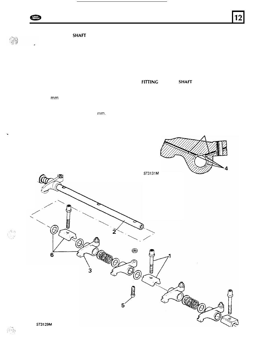
Remove the five rocker shaft retaining  bolts 

and  withdraw  the  bearing  caps, 

rockers, 

washers  and  springs from  the shaft. 

Examine 

t h e  rocker shaft  for wear and  discard 

if 

the  bearing  surface is  wom,  scored or pitted. 

Check  also that 

the oilways are  clear. 

Inspect 

the rockers and  discard 

if 

the pads  are 

worn.  It  is 

n o t  permissible 

to grind  pads 

in 

an 

attempt t o  reclaim  rockers. 

Renew  the bushes 

if 

the clearance exceeds 

0,127 

(0.005 

in). Press  in  replacements 

ensuring  that  the pre-drilled  holes  align 

with 

those  in  the  rockers  and  machine  the  inside 
bore 

of  the  bushes 

to  18,018 

The  rocker 

arm  and  bush 

oil 

drillings are  shown  in  the 

cross section  illustration. 

Examine the  tappet adjustment screws  and 
check that  t h e  ball  end 

is  not worn  or pitted 

and  that 

t h e  lubrication  hole  is  clear. 

Assemble  the  rockers,  bearing  caps,  new 
springs  and washers  to the shaft noting where 
the washers  are fitted.  Hold  the  assembly 
together with  t h e  

five 

rocker  shaft  retaining 

bolts. 

Push 

rods 

1 .   Examine  the push  rods  and  renew  any that 

are 

bent 

or where the ball 

or 

cup ends are worn 

or pitted. 

2. 

Fit  the push  rods 

to the engine ensuring  that 

the  ball-end  locates  properly  in  each 
camfollower  slide. 

ROCKER 

1. 

Ensure that  a new cap is  fitted 

to  each  valve 

stem before  fitting  the rocker  shaft. 

2. 

Fit  the rocker shaft t o  the cylinder head 

ensuring  that  t h e  retaining  bolts and push  rods 
are  correctly located  then  evenly tighten 

the 

bolts 

to correct  torque. 

79 

Adjust tappet  clearances 

ENGINE 

DEFENDER 

WARNING 

the crankshaft 

is  rotated with 

excessive valve  clearances,  it  is  possible that 
the  push  rods may become dislodged from 
the  tappet  seating and fracture the tappet 
slide. 

To prevent damage, eliminate all  clearance from any 

loose rockers  before tuming the crankshaft t o  adjust 
clearances. 

1. 

Tum  the engine over until  number eight valve 

(counting from front 

of engine) is  fully open. 

2. 

Using  a 

(0.008 

in) 

feeler gauge adjust 

the clearance 

of  number o n e  valve. 

Continue t o  adjust the remaining  tappets in  the 
following  sequence: 

Set 

No. 

tappet with 

No. 

valve fully open. 

Set 

No. 

tappet with 

No. 

valve  fully  open. 

Set 

N o .  

tappet with 

No. 

valve  fully open. 

Set 

No. 

tappet with 

No. 1 

valve fully open. 

Set 

No. 

tappet with 

N o .  

valve  fully open. 

Set 

N o .  

tappet with 

No. 

fully open. 

Set 

No. 

tappet with 

No. 

valve  fully  open. 

Rocker  cover and crankcase ventilator 

If 

necessary  release t h e  single bolt  and  remove 

the oil  separator ventilation  valve  unit,  from 
the side 

of  the rocker  cover and thoroughly 

clean. 

Its  function 

is  t o  separate t h e  oil  from  the crankcase 

ventilation  atmosphere, allowing  the oil  t o  retum  t o  
the sump and t h e  residues t o  

be drawn into the 

chamber where they are bumed. The 

unit  also contains  a diaphragm  valve which  controls 
the purge  rate 

of  the crankcase fumes. The 

operation 

of  the valve  may 

be tested  as follows. 

Test 

2. 

procedure  crankcase ventilator 

With  the unit  removed  from t h e  

rocker cover 

seal 

off 

the two ports illustrated  and apply a 

vacuum  t o  the third  por. 

As 

t h e  vacuum  pump 

is 

operated the diaphragm  valve will  b e  heard 

t o  seat. While  holding t h e  vacuum  unseal 
either 

of  the other 

two 

ports and the diaphram 

valve will 

release. 

test,  indicates  that the diaphragm 

is  punctured 

and  the unit should  be renewed. 

3.  Failure 

of the diaphragm valve t o  seat during 

4. 

Refit 

the unit  using  a new rubber 

ring. 

Fitting 

rocker 

cover 

5. 

Apply  a  continuous bead 

of 

Hylosil  which 

starts and  finishes 

10 

each side 

of  the half 

m o o n  grooves  at both e n d s  

of 

the rocker shaft 

and  press  the seals into position. 

6. 

Locate a new seal in  the rocker  cover and fit 

t h e  cover t o  t h e  cylinder  head securing with 
t h e  three special bolts  and  conical washers. 

Tighten  the bolts evenly t o  t h e  correct torque 

&-


and  reconnect  t h e  ventilation  hoses. 

80 

... 

DEFENDER 

ENGINE 

HEATER  PLUGS 

1. 

2. 

If 

necessary check the operation 

of  each 

heater plug  before  fitting  and  tighten  t o  the 
correct torque,  d o  not over-tighten. 
Connect t h e  electrical harness  t o  the plugs  and 

secure with  t h e  single nut  and washer.  Ensure 
that each  s p a d e  terminal 

is 

fitted so that 

neither the terminal  nor the insulation  touches 
the cylinder  head,  o r  oil  separator. 

INJECTORS A N D  

PIPES 

1. 

Ensure  that  the injector and  seating  in  t h e  

cylinder  head  is  clean then  lightly grease a new 
copper washer in  position  o n  the injector. 

2. 

Fit 

the injectors with  the spill return  outlet 

facing  towards the rear 

of 

the engine and 

secure each with  a clamp and  nut. The clamps 
are slightly  curved  and the convex 

side should 

be fitted  uppermost.  Tighten  the nuts  t o  the 
correct  torque. 

3. 

Fit  the spill  return  rail  t o  the injectors,  noting 

that  there are two copper washers and o n e  
must  be fitted each side 

of  the retaining  union 

screw. The in-board  washer locates  in  a recess 
in  the injector. 

Do 

not over-tighten  t h e  screws. 

4. 

Fit 

the banjo-union  end 

of  the spill return  rail 

t o  the rear 

of 

the injector pump and  secure 

with  a copper washer each  side 

of 

the banjo 

and  the union  bolt. 

5. 

Fit  t h e  injector  fuel supply pipes  securing each 
end 

of 

the pipes t o  their  respective  locations 

loosely,  then  tighten  evenly. 

D o  

not, 

however, 

over-tighten. 

Commencing  at the front 

of  the engine connect 

the pipes as 

follows: 

A. 

To number 

injector. 

To number 

injector. 

C. To number 

injector. 

To 

number 

injector. 

81 

DEFENDER 

FUEL 

SYSTEM 

... 

FUEL INJECTION PUMP 

Service 

Repair 

No. 

Remove and refit 

Special tools:- 

Flywheel  timing  pin 

LST  128 

Pump gear retaining  tool 

LST 

Pump timing  pin 

LST 

1. 

Remove the bonnet and disconnect the 
battery. 
Drain  the cooling  system. 

3.  Remove  the fan  and viscous coupling  assembly 

see operation  26.25.19 

4. 

Remove the fan  cowl 

see operation  26.25.11. 

Disconnect  the lower cooling  hose from the 

waterpump. 

6 .  

Remove the oil  filler cap 

so 

that the position 

of 

number o n e  cylinder valve 

rockers can  b e  s e e n  

t o  assist in  obtaining T.D.C. 

7. 

Tum  the crankshaft 

to 

align  the 

mark  o n  

the crankshaft damper with  the the w e b  o n  t h e  
front  cover plate.  At  the same time check  that 
the valves 

of  number o n e  cylinder are closed. 

Remove the blanking  plug  from  the  bottom 

of 

the flywheel  housing 

and 

fit  the timing  pin  LST 

Check that  the pin  can  b e  inserted  into 

the appropriate slot  in  the flywheel.  Note  that 
there are 

two 

slots in  the flywheel  t h e  

narrowest  o n e  being that  which  determines 

T.D.C.  for this  engine. 

9.  Remove the injector  pump hub blanking  plate. 

Through the 

"U" 

shaped slot in  the pump hub 

into the pump body.  Ensure  that  the pin  fits 
easily and 

is  fully inserted. 

10. 

Insert the injector pump timing  pin  LST 

LST 

Continued 

82 


Content   ..  173  174  175  176   ..