Defender 90 / 110 / 130. Manual - part 174


  Index      Land Rover     Defender 90 / 110 / 130 - service repair manual


Search            


Content   ..  172  173  174  175   ..


Defender 90 / 110 / 130. Manual - part 174


DEFENDER 

ENGINE 

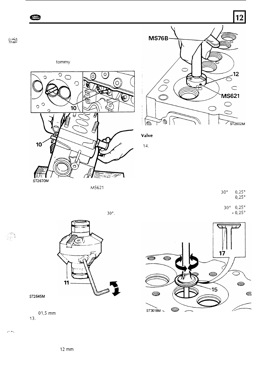
10.  insert the assembled  pilot  into the valve guide 

from the combustion  chamber side 

of the 

cylinder head  until  the shoulder contacts the 

valve  guide and the whole 

of  the collet is 

inside the guide. To lock  the pilot  in  the guide 
turn  the 

bar  clockwise  whilst  holding 

the knurled  knob. 

....... 

refacing 

11. 

Check that the seat cutter 

is  assembled 

correctly  using  the 

key MS76  ensuring that the 

angled  end 

of  each cutter 

is 

towards  the seat 

and  set 

so that the middle of  the blade 

contacts the seat first. O n e  end 

of  the  cutter is 

angled  at 

45" 

and the other end 

is 

12.  Using  very  light  pressure tum the cutter 

clockwise  until  the angled  face 

is  approximatly 

wide. 

operation  smear a small quantity 

of  engineers' 

blue round  the valve  seat and  revolve  a 
correctly  ground valve against the seat. 

good 

seating will  produce  a continuous fine polished 
line  around  the valve  face. 

slight  gap 

of 

not 

more than 

in  t h e  polished  line, can  b e  

corrected by  lapping. 

To 

check the effectiveness 

of 

the cutting 

Valves that are satisfactory 

for further service 

can  be refaced. This  operation should be 
carried  o u t  using  a valve  grinding  machine. 
Only t h e  minimum 

of  material should b e  

removed from t h e  valve  face 

to 

avoid  thinning 

of  the valve  edge. The valve 

is 

refaced 

correctly whan  all  pits  are removed  and  the 
face 

is 

concentric with  the stem. 

Inlet  valve  seat f a c e  

Exhaust  valve  seat face 

45" 

Inlet  valve face 

Exhaust  valve face 

45" 

75 

ENGINE 

DEFENDER 

Lapping 

valves 

15. 

To 

ensure a 

gas tight  seal between  the valve 

face and valve  seat it 

is  necessary  t o  lap-in  the 

appropriate valve  t o  its seat.  It 

is  essential  t o  

keep t h e  valve  identified  with  its seat o n c e  the 
lapping-in  operation  has  been  completed. 
Unless  the faces t o  be lapped  are  in  poor 

condition  it  should only b e  necessary  t o  use 
fine valve  lapping  paste. 

16. 

Smear a small  quantity 

of  paste  o n  the valve 

face and lubricate t h e  valve  stem with  engine 
oil.  Insert the valve  in  the appropriate guide 
and  using a suction type valve  lapping  tool 
employ a light  reciprocating  action while 
occasionally  lifting the valve 

off 

its seat and 

turning  it 

so that the valve  returns  t o  a 

.  . 

different position  on the seat. 

17. 

Continue the  operation  until  a continuous matt 

grey  band round  the valve  face 

is  obtained. 

To 

check that the lapping  operation 

is  sucessful, 

wipe 

off 

the valve  paste  from  the valve  and 

seat and  make 

series 

of pencil  lines across 

the valve  face. 

18. 

Insert  the valve into t h e  guide and while 

pressing  the valve  o n t o  the seat revolve t h e  

valve  a quarter 

of  turn  a few times. 

If 

all  t h e  

pencil  lines  are cut through  n o  further lapping 
is  necessary. Thoroughly wash  the cylinder 
head  ensuring n o  lapping  paste  remains  before 

fitting  the valves. 

19. 

Position  the cylinder head with  the combustion 

face uppermost,  lubricate  and  insert the valves 
into their  respective guides. To check the valve 
head  stand-down  or t h e  correct dimension 

of 

the valve  head  below  the combustion face,  use 
either a dial  test  indicator or a straight  e d g e  
and feeler gauge as follows. 

20. 

Hold  t h e  straight e d g e  across the centre 

of 

each valve  in  turn  and  measure  the gap 
between  the valve  head  and  straight edge. The 
correct dimension  should  b e  

t o  

(0. 

040 

t o  

in). Using  a dial  gauge zero t h e  

gauge o n  the  combustion face then  move the 
stylus  across t o  the valve  head  and note t h e  
reading. 

Assembling valves 

to 

cylinder head 

21. 

Insert  the valves  t o  their respective guides and 
locate a spring  protection washer over each 

guide.  Fit  new 

oil  seals t o  all  the valve  guides 

with  t h e  garter spring  uppermost.  Ensure  that 
the seals  fully locate o n  valve  guides. 

76 

DEFENDER 

ENGINE 

... 

22. 

Fit  a spring and cup t o  each valve and 

compress with  special  service  tool 

or 

a suitable altemative.  Retain  with  the 
multi-groove  cotters ensuring  that  they  are 
fully located  in  the valve stem and cup. 

. . 

Thermostat  and housing 

0.61 

t o  

0.80 

0.71 

t o  

23.  If  necessary remove the temperature 

transmitter and temperature sensor from  the 
housing. 

24.  Release the three bolts  securing  the thermostat 

cover and  lift  o u t  the thermostat. The 
thermostat  may  be tested  by  immersing  it  in 
hot water 

of  a  known  temperature and 

comparing its  operation with  the temperature 
range  stamped o n  the flange.  Any  leakage 

of 

wax 

(which 

is  the colour 

of  copper) from 

around  the 

pin  of  the thermostat, 

indicates that  it 

is  faulty and  should  be 

renewed. 

0.024 

to 

0.0275 

t o  

0.0314 

25.  The thermostat housing  may  b e  removed from 

the cylinder  head  at  this stage and 

if 

necessary 

the gasket  renewed. 

26.  The  "jiggle pin" which  allows  any air t o  escape 

from  below the thermostat,  may  b e  fitted  in 
any position.  Renew  the gasket when fitting 
the thermostat and apply a  little  Hylomar 

sealant 

to the threads of  temperature sensor 

and transmitter  before screwing into  position. 

FITTING 

CYLINDER  H E A D  

Piston  protrusion  and gasket  selection 

Before 

fitting the cylinder  head,  the protrusion 

of 

the pistons  above the block  face must  b e  checked 
in  order that the correct  thickness  gasket  may  be 
selected  from  the range 

of  three.  The height 

of 

all 

the pistons  above the cylinder  block  must  be 
measured and the thickness 

of 

the gasket  selected 

is 

based  upon the largest  value 

of  dimension 

'A', 

as 

illustrated.  This  dimension, however,  must not 
exceed 

0,8 

(0.032 in). 

Three thicknesses 

of  gasket are available  and each 

size can  b e  recognised  by  the number 

of 

identification  holes  punched  in  the side 

of  the 

gasket as illustrated.  The table  below gives the 
details 

of  t h e  gaskets available. The thickness  of 

gasket fitted can 

be  seen when the cylinder head 

is 

fitted  since  the identification  holes  can 

be  seen 

protruding  from  the right  hand  side 

of  the engine 

towards  the rear. 

Number 
of  holes 

Metric 

Imperial 

Gasket 

ERR0382 

ERR038 

ERR0384 

77 

ENGINE 

DEFENDER 

Clean  the cylinder block  combustion  face  and 

the crankshaft 

so that  number o n e  and 

number  four pistons are at 

D.C.  Use  a dial 

test indicator t o  determine  the highest travel 
of  t h e  piston  then 

zero 

the gauge and move 

the stylus over t o  the cylinder block  and  note 
the reading.  Repeat the  procedure on the 
remaining  pistons.  The  highest  figure obtained 

will  determine the gasket  selected. 

2. 

Place  the selected the head  gasket  in  position 

o n  the cylinder block 

so 

that  the identification 

holes  are towards  the rear o n  the right-hand 

side. 

Clean  the cylinder  head  face and 

if 

preferred, 

guide studs may  be fitted 

to the cylinder block 

t o  facilitate the lowering 

of 

the head  into 

position.  Locate the head  over the two 
dowels. 

oil, and fit to the positions illustrated 
according to length  and diameter. Tighten  the 
bolts  down 

so 

that  the heads just  make 

contact with  the cylinder  head. 

Now, 

in  the 

sequence shown, tighten 

all 

the 

down 

40 

with  a suitable torque wrench. 

4. 

Lubricate  the threads 

of  new bolts,  with  light 

Bolt  sizes: 

locations 

3, 

5, 

1 2  and 

13 

M 1 2  

locations 

1, 

2, 

4, 

7, 

9, 

10, 

14, 15, 

16, 

17, 

1 8  

ST2619 M 

5.  Attach  the special service 

tool  degree disc 

to a  power bar.  Make  a suitable pointer 

from welding  rod  and attach  it  t o  a  bolt 

screwed  into a 

rocker shaft securing bolt  hol. 

6 .  

Tighten  all  the  bolts  down through  an  angle 

of 

60" 

strictly  in  the sequence illustrated. 

As 

each 

bolt 

is 

tightened  scribe a  line  across the head 

with  a  piece 

of  chalk  o r  crayon  t o  identify 

which  bolts  have  been  tightened,  then  tighten 
each bolt  a further 

60" 

again  in  the correct 

sequence t o  complete the tightening 
procedure.  Re-positioning 

of  the pointer 

will, 

n o  doubt, 

be 

necessary t o  reach  all  bolts. 

CAUTION: 

It 

is  important that the double 

torquing  procedure 

is  observed and that  on 

no account should  the total  angle 

of 

120" 

be performed  in  o n e  operation otherwise 
damage  and distortion 

of 

the cylinder head 

may occur. 

78 


Content   ..  172  173  174  175   ..