Defender 90 / 110 / 130. Manual - part 173


  Index      Land Rover     Defender 90 / 110 / 130 - service repair manual


Search            


Content   ..  171  172  173  174   ..


Defender 90 / 110 / 130. Manual - part 173


DEFENDER 

ENGINE 

WATER  PUMP  INSPECTION AND 

The water pump 

is 

not  a  reconditionable  unit  but  its 

condition  can  be determined  by  the following 
checks 

... 

1. 

2. 

Spin the  p u m p  spindle and listen 

for bearing 

noise,  also  push  and pull  the spindle and 
check for sideways movement. 

If 

the  bearing 

is 

in  g o o d  condition  the clearance between  the 

and  the pump body should  not vary. 

Inspect  the vent hole in  the  pump body for 

signs 

of 

coolant 

or 

lubricant  leaks. 

If 

there is 

any  evidence 

of  leakage,  the pump should be 

renewed. 

Fitting water 

pump 

3. 

Lightly grease a new joint  washer and place  it 
in  position  o n  the timing  cover. 

Clean the threads 

of  the water pump  retaining 

bolts and apply Loctite 

572 

thread  lubricant 

sealant t o  the threads 

of 

the long  bolts  which 

penetrate  into the cylinder  block. 
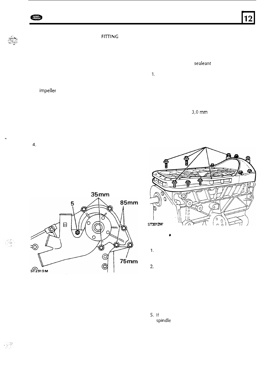
5. 

Fit  t h e  pump t o  the cylinder  block  and secure 
in  accordance with  the bolt  chart. Tighten  the 

six 

bolts and o n e  nut evenly  t o  the correct 

torque. 

6 .  

If 

separated, fit the fan  blades t o  the viscous 

coupling with  the four screws. Fit  the fan  and 

viscous  coupling assembly t o  the water  pump 
spindle noting  that  it  is  secured with  a 

left-hand  thread. 

I f  

air  conditioning 

is 

fitted  d o  

not at this  stage fit  the drive  belt  until  the 
compressor belt 

is  fitted. 

Fitting  ladder frame 

Since the sealant specified t o  seal the ladder frame 

to 

the crankcase cures within  fifteen  minutes it 

is 

important  t o  fit sufficient bolts 

to ensure adequate 

compression while the 

cures. 

Clean  both  sides 

of 

t h e  ladder frame and 

remove  all  traces 

of old  sealant.  Check that  the 

frame is  not distorted  and 

is 

free 

from burrs 

and damage o n  the  mating faces that  could 
cause 

oil  o r  bypass 

gas t o  leak. 

2. 

Coat both  faces with  Hylogrip  Primer 

to 

clean 

and  hasten  curing  then  apply a  bead 

of 

"Hylogrip 

2000" 

wide t o  t h e  mating 

face with  the crankcase. 

3. 

Fit  ten securing  bolts through  the ladder frame 

flange  and  two more through  the sump face  as 
illustrated. Tighten  all  bolts  evenly to the 
correct torque. 

OIL 

3. 

4. 

PUMP 

OVERHAUL 

Bend  back  the 

lock washer  and  release the  nut 

securing  the strainer  t o  the oil  p u m p  body  and 
remove  the. strainer and sealing  ring. 
Remove  the four bolts and washers,  lift 

off the 

oil  pump cover and remove the driving and 
driven gear. 
Remove  the oil  pressure 

relief 

valve  plug  and 

sealing washer.  Withdraw the relief  valve  spring 
and plunger and examine 

for wear and scores. 

Examine the gears 

for wear,  scores and pitting 

and renew 

if 

necessary.  Note:  Gears must  b e  

renewed  in  pairs  only. 

showing signs 

of  wear the driven  gear 

may 

be 

renewed. 

71 

ENGINE 

DEFENDER 

6 .  

Clean  all  the components then  install  both 
gears  into the body ensuring  that  the recessed 

e n d  

of 

the driving  gear is  uppermost. 

7. 

Place  a straight e d g e  across both gears as 

illustrated  t o  measure the end float 

of 

each 

using  a 

feeler gauge. 

Also 

check the gear 

backlash  and  the clearance between  the gears 
and  pump body. The  correct clearances are 
given  in  the data section. 

8. 

Examine the gear thrust  face o n  the pump 

cover,  any slight scratches  may  be erased  by 
rubbing 

on  fine emery cloth  o n  a flat  surface. 

Pump 

assembly. 

9. 

With  gear 

correct,  lubricate and fit 

the driven  gear to t h e  spindle and  install the 
driving  gear with  the counter bored  splined 
e n d  

of  the gear uppermost  in  the pump 

housing. 

10. 

Fit  the cover locating  it  over the two dowels 
and 

secure with  the four bolts until  the 

strainer 

is  fitted. 

11. 

Install the spring into the relief  valve  then 

lubricate  and insert  t h e  valve into the relief 

valve  bore retaining  with  the sealing washer 
and plug. 

Fit  a  new '0' ring t o  the oil  strainer pipe and 

insert  into the pump  body and loosely secure 

with  the 

lock washer  and  nut. 

1 3 .  

Secure the strainer bracket t o  the pump  body 
and tighten  the four 

screws. Tighten  the 

strainer  pipe nut and  secure with  the 

lock  tab. 

14. 

Insert the pump drive  shaft  and check that  the 

gears  are free t o  operate before refitting  t o  the 
engine. 

72 

DEFENDER 

ENGINE 

Fitting 

oil  pump 

1 5 .  

Ensure  that  the oil  pump drive shaft 

is  located 

in  the appropriate spiines and  fit  the oil  pump 

and strainer  assembly into the cylinder block 
using  a  new  gasket, tighten  the two 

t o  

the correct torque. 

Fitting the sump 

16. 

Ensure  that all  traces 

of 

old  sealant are 

removed  from  the sump joint  face and that  the 

sump 

is  thoroughly  clean  inside and out. 

Remove the 

two 

two 

bolts  securing  the ladder 

frame t o  the cylinder  block  to allow  fitting 

of 

the sump. 

18. 

Apply  a 

wide  bead 

of 

black  t o  the  sump face and 

fit 

the sump. 

19. 

Install and  tighten  the twenty remaining  bolts 

t o  the correct  torque.  Note that  the three long 
bolts  pass  through  the sump and ladder frame 
into the front  cover. 

CYLINDER HEAD OVERHAUL 

CAUTION: 

Since the cylinder head 

is 

manufactured from  an aluminium alloy care 
must 

be 

taken  t o  ensure that the 

combustion face,  in  particular, 

is  not 

damaged 

o r  

scratched  by  placing  it 

on a 

hard 

or  abrasive surface while  carrying out 

the overhaul  operations. 

1. 

Using  valve spring  compressor 

MS 

151 

9A 

or 

suitable altemative,  remove the valve  and 
spring assemblies identified  t o  their original 
locations. 

73 

2. 

Discard  the valve  springs  and valve guide  oil 

seal.  Remove carbon  deposits from  the valves 
and  combustion chambers and degrease all 
parts  ready  for examination. 
Examine the cylinder  head  for damage and 
distortio.  Inspect  the valve seat inserts 

for 

damage.  Seat inserts  that  are beyond  repair 
and  require  renewal should  be replaced  by a 

skilled specialist  in  this  type 

of  work. 

4. 

Examine each valve guide and valve  stem 

for 

wear  and damage.  Suspect guides should b e  
checked 

by 

inserting  a  new valve into the 

guide  and 

the valve  lifted  approximatly 

clear 

of  the seat the valve head  should not 

rock 

more than 

(0.006 

in). 

If 

the valve 

head  movement  exceeds 

(0.006 

in) 

the guide should  be renewed. 

5. 

inspect  the valves 

for 

wear  and damage. Valve 

heads that  are burnt and cracked  should 

be 

renewed.  So should valves  which  are bent and 
distorted.  Insert  the valve  into a new guide  and 
check the side movement  as described above 
to determine the wear o n  the valve stem. 

ENGINE 

DEFENDER 

Renew valve 

guides 

6. 

Support the cylinder head,  combustion 
chamber uppermost o n  pieces 

of 

timber 

of 

sufficient thickness  t o  allow clearance 

for 

the 

inlet  or exhaust f o r  the valve  guides t o  b e  
driven  o u t  using  special tool 

7. 

Turn  the cylinder head 

over 

so that  the 

combustion face 

is  downwards.  Lubricate  the 

new valve  guides and using  special  service 

tool 

LST 

130 

and depth gauge 

RO 

press 

the guide into position  t o  the depth 
determined 

the 

in). 

Reface 

valve seat  inserts 

8. 

9. 

The special s e t  

of 

hand tools recommended 

tightly  into new 

or 

guides to ensure that 

the valve  seat 

is  concentric with  t h e  valve 

guide. The refacing 

tool  has  tungsten carbide 

cutters  and  can  b e  used t o  c u t  a  new seat in 
the insert. The valve  seat cutter 

is 

numbered 

the handle  s e t  

and the pilot 

Loosely  assemble t h e  pilot  in  the sequence 
illustrated.  Ensure  that  the chamfered e n d  

of 

the expander 

is 

towards the collet. 

for  refacing  include  expandable pilots  that  fit 

74 


Content   ..  171  172  173  174   ..