Defender 90 / 110 / 130. Manual - part 176


  Index      Land Rover     Defender 90 / 110 / 130 - service repair manual


Search            


Content   ..  174  175  176  177   ..


Defender 90 / 110 / 130. Manual - part 176


DEFENDER 

FUEL 

SYSTEM 

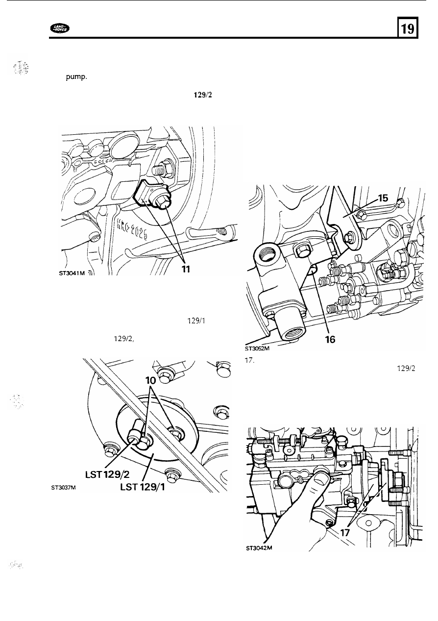
11.  Slacken  the p u m p  locking  screw and remove 

14. 

Remove  the injector pipes  and disconnect  the 

the keeper plate.  Tighten  the screw t o  

lock t h e  

CAUTION: 

Once the timing pin  LST 

is 

inserted  and the pump shaft locked, 

no 

attempt  must  be made 

to 

rotate the 

crankshaft. 

Main  fuel supply pipe. 

following items  from the injector pump. 

Throttle cable. 
s t o p  control solenoid lucar. 
Spill return  pipe. 
Turbo charger  boost hose. 

12.  Remove  the pump drive gear three  retaining 

bolts  and remove the 

lock  plate  and timing 

pin. 

13.  Fit  the pump gear retaining  tool 

LST 

and 

align and tighten the two bolts.  insert  the 
timing  pin  LST 

again,  through  the  hole 

provided  in  t h e  retaining  tool. 

15.  Remove  the injector pump  rear support 

bracket. 

16. 

Remove the 

oil 

filter adaptor rear  attachment 

bolt t o  allow clearance  for the pump t o  be 

withdrawn. 

Remove the pump three retaining  nuts and 

withdraw  the pump and gasket, with 

LST 

18. 

Fit  blanks  t o  the inlet  and  outlet  ports t o  
prevent  entry 

of 

dirt.  Slacken the locking 

screw, 

fit 

the keeper  plate  and tighten  t h e  

screw. 

83 

Reff 

FUEL 

SYSTEM 

DEFENDER 

19. 

20. 

21. 

Clean  the pump flange and front cover mating 
face and  place  a new gasket  in  position  over 

the the studs. 
Fit  the timing  pin  LST 

t o  the  pump, 

if 

necessary,  rotate t h e  pump t o  enable the pin 
easily  and fully. 
Slacken  the pump  locking  screw, remove t h e  
keeper plate  and  tighten the screw t o  lock  t h e  

21 

20 

22. 

23. 

24. 

25. 
26. 

Fit  the pump t o  the front cover and  drive gear 

and secure with  the three nuts tightening 
evenly t o  the correct  torqu. 
Fit  t h e  rear support bracket  t o  the cylinder 
block  and secure t h e  pump t o  the bracket. 

Tighten  all  bolts  the the correct torque. 

Fit  t h e  oil  filter adaptor rear attachment  bolt. 
Connect the items listed  in  instruction 

14. 

Fit  t h e  injector  supply pipes securing each e n d  
to their respective  locations, loosely  then 

tighten  evenly  but 

do not over tighten. 

Commencing  at t h e  the front 

of 

the engine 

connect the pipes as follows:- 

t o  number o n e  injector. 

t o  number two  injector. 

C t o  number three injector. 
D  t o  number four injector. 

27. 

28. 

30. 

31. 

1. 

3. 

4. 

6. 

32. 

33. 

Remove  t h e  p u m p  timing  pin  and  the p u m p  

gear retaining  tool 

LST 

insert t h e  pump timing  pin  again  and fit  t h e  
gear 

lock  plate and secure with  the three  bolts 

and tighten 

to the correct torque. 

Remove  the timing  pin.  Unlock  the pump,  fit 

the 

keeper plate  and tighten the bolt. 

To 

check  that the p u m p  timing 

is  correct,  turn 

the crankshaft 

two  complete revolutions  and 

check that the timing  pin  LST 

can  b e  

inserted  easily and fully into t h e  pump.  at the 
same time check  that t h e  flywheel timing  pin 
can  also  b e  inserted  in  t h e  flywheel  slot. 
If,  with  t h e  flywheel timing  pin  located,  t h e  
timing  pin  cannot  b e  inserted  cleanly into the 
pump, 

out t h e  following instructions:- 

Turn  the crankshaft  t h e  small amount necessary 
to  enable t h e  timing  pin  t o  b e  inserted  into 
the pump. 
Remove t h e  

keeper plate a n d  lock the pump. 

Slacken  t h e  three p u m p  gear retaining  bolts. 
Tum  the crankshaft 

to T.D.C. 

Check that t h e  timing  pin 

is 

an easy fit  in  the 

pump and  that  t h e  flywheel  timing  pin  locates. 
Tighten  t h e  p u m p  gear retaining  bolts t o  the 
correct torque. 
Unlock  t h e  pump, fit  t h e  keeper plate  and 
tighten  t h e  bolt.  Remove t h e  timing  pin  from 
the the p u m p  and the timing  pin  tool  from  the 
flywheel. 

Fit  the p u m p  aperture cover with  a  n e w  gasket 
and  secure with  the screws. 
Connect t h e  cooling system bottom  h o s e  t o  
the waterpump. 

Continued 

84 

.. 

..... 

...... 

DEFENDER 

FUEL 

SYSTEM 

Place  the fan  cowl in  position  but 

do not 

secure it  t o  t h e  radiator  until  t h e  fan  and 
coupling  is  fitted. 

35.  Fit  the fan  and viscous  coupling  assembly t o  

the waterpump spindle. Tighten  the 

left hand 

thread  to t h e  correct torque  using  a 
bar  in  the hole provided  in  the fan  pulley t o  
restrain  the coupling. 

36.  Secure the fan cowl  t o  the radiator with  the 

two 

nuts. 

Fit  the t o p  coolant hose. 

38. 

the cooling system with  t h e  correct 

concentration 

of  water  and anti-freeze  s e e  

operation  26.10.01. 

AIR 

CLEANER 

Service Repair  No. 

19.10.01 

Remove 

and 

refit 

1. 

Disconnect  t h e  hose from  the turbo charger 

compressor housing t o  air cleaner. 

2. 

Disconnect,  from the air cleaner,  the engine 

breather hose. 

3. 

Disconnect from the air cleaner,  t h e  air inlet 

5. 

To release  and remove the air cleaner from its 

mounting  cradle, twist  the body 

of  the air 

cleaner  anti-clockwise  (viewing it  from  the 
front 

of  the engine) and  remove it  from the 

vehicle. 

Renewing  e l e m e n t  

and 

remove the e n d  cover. 

7. 

Unscrew  the wing  nut  and withdraw the 

8. 

Clean  the interior 

of the casing and  cover. 

9. 

Fit  a  new element,  fins  leading,  into the casing. 

10.  Secure the element with  the wing  nut. 
11.  Fit  the end cover and aline the two arrows. 

element. 

Refitting 

12.  The two clips o n  the side 

of  the casing locate 

in  the square slots in  the air cleaner mounting 
cradle. 

It 

is 

necessary therefore, t o  twist  t h e  air 

cleaner clockwise into its  final  position  and 
ensure that the clips  engage in  the slots. 

13.  Secure the air cleaner with  the two fastners. 

14. 

Connect all  the hoses,  reversing  instructions 

to 

15. 

Finally, reset  the element change indicator, 

where fitted, by depressing the  button. 

85 

TURBO 

CHARGER 

FUEL 

SYSTEM 

DEFENDER 

Service Repair 

No. 

Remove  and refit 

Remove the bonnet  and disconnect t h e  
battery. 

2. 

Remove the turbo  charger heat shield. 

3.  Disconnect the exhaust front 

pipe 

from  the 

turbo  charger 

elbow. 

4. 

Release the front exhaust pipe  from the 

support bracket  attached t o  t h e  cylinder 

block. 

5.  Remove the five nuts and  remove the elbow 

from  the turbo  charger. 

6 .  

Remove the air inlet  hose from the air cleaner 
and  turbo charger. 

7. 

Disconnect, from  t h e  turbo charger,  t h e  
bottom  hose from t h e  intercooler. 

8. 

Remove t h e  boost  pressure  pipe from  t h e  
turbo 

piece. 

9. 

Slacken  the turbo charger oil  feed  pipe  clamp. 

10. 

Disconnect the 

oil 

supply 

pipe 

from  t h e  turbo 

charger centre housing. 
Release  the oil  return  drain 

pipe  from the 

turbo  charger. 

Remove t h e  four nuts and lift  the turbo 

charger from the exhaust  manifold  and retrieve 
the steel joint  washer. 

Refitting 

13. 

Fit  the steel joint  washer t o  the t o  the exhaust 
manifold 

86 


Content   ..  174  175  176  177   ..