Defender 90 / 110 / 130. Manual - part 120


  Index      Land Rover     Defender 90 / 110 / 130 - service repair manual


Search            


Content   ..  118  119  120  121   ..


Defender 90 / 110 / 130. Manual - part 120


BR

A

KING SYSTE

Remove and overhaul expander assembly 

7.  Remove the rubber dust cover. 

8. 

Remove the expander and draw link. 

9.  Remove the retainer spring plate. 

10.  Remove the locking plate. 
11.  Remove  the  packing  plate  and  withdraw  the 

12.  Remove the two plungers and rollers. 

13. 

Clean all parts in Girling cleaning fluid and allow to 
dry.  Examine the components for wear and discard 

if unsatisfactory. 

expander assembly from the back-plate. 

Assemble expander assembly 

14.  Grease and fit the expander and drawlink. 
15.  Grease and  fit the plungers  and rollers noting that 

the highest  end 

of 

the ramp on the plungers is fitted 

towards the back-plate.  Secure the assembly with a 
rubber band to prevent the plungers falling out and 

place 

to one side for assembly to back-plate. 

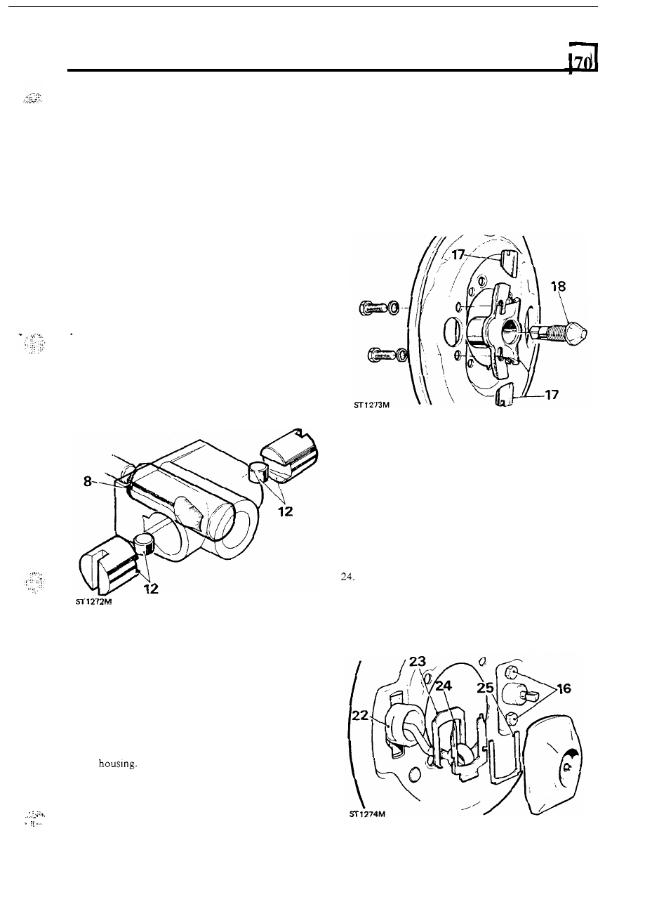
Remove and overhaul adjuster assembly 

16.  Remove  the  two  bolts  and  withdraw  the  adjuster 

17.  Remove the plungers. 
18.  Screw  the  adjuster  cone  inwards  to  remove  from 

19.  Clean the parts in Girling cleaning fluid and discard 

assembly from the back-plate. 

t h e  

any unsatisfactory components. 

Assemble adjuster assembly 

20.  Grease and screw in 

the 

adjuster cone. 

21.  Grease and  fit  the adjuster plungers  and  align  the 

chamfered  ends with  the adjuster cone. Note  that 
the  two plungers  are identical  and  can  be  fitted 

to 

either  bore.  Secure  the  assembly  with  a  rubber 
band to prevent the plungers falling out. 

ASSEMBLE 

NOTE:  If  the brake linings are oil-soaked check and  if 
necessary renew the output shaft oil seal. 

22.  Position the expander assembly on the inside of  the 

back-plate  and  secure with  the following plates  at 
the rear 

of the back-plate. 

23.  Packing piece. 

Locking plate. 

25.  Retainer spring. 
26. 

Fit the rubber dust cover. 

continued 

... 

B

RA

KING S

YSTEM 

27.  Fit the adjuster assembly to the back-plate with the 

two bolts but do not fully tighten at this stage. 

28.  Fit  the  back-plate  assembly  and  mud  shield  to  the 

transfer box  with  the  four bolts  and  tighten  to the 
correct torque. 

29. 

Fit  new pull-off springs  to relined  brake  shoes and 
fit 

to  the  back-plate.  Note that  the  fully lined  end 

of  the  lower  shoe  must  be  toward  the  expander 
assembly and the fully lined  end 

of  the  upper shoe 

towards the adjuster assembly. 

29 

30.  Fit the brake drum and secure with the two screws. 
31.  Connect  the  expander  drawlink  to  the  actuating 

lever with a new clevis pin, washer and split pin. 

32.  Turn  t h e  adjuster cone fully in  and tighten  the two 

retaining bolts 

left 

slack in instruction 27. 

33.  Slacken  off  the  adjuster  two  ‘clicks’  and  firmly 

apply  the  hand  lever  to  centralise  the  shoes. The 
drum should 

rotate freely. 

34.  Adjust  the  handbrake  cable 

t o  

give  the  pawl  two 

‘clicks’ free  movement  on  the  ratchet  before  the 
third  ‘click’  fully  expands  the  shoes  against  the 
drum. 

35.  Connect the propeller  shaft and evenly tighten  the 

retaining 

to the correct torque. 

Remove  chocks  from  wheels  and  connect  the 

battery. 

BLEEDING 

THE BRAKES 

Primed System 

Bleed  the  front  brakes  first  starting  with  the  wheel 
nearest to the master cylinder. 
1.  Attach  a  rubber  tube  to  the  bleed  screw  and 

immerse  the  other  end 

in 

a  glass  jar  containing  a 

quantity of clean, new recommended brake fluid. 

2.  Check that the fluid reservoir is full to 

the maximum 

mark. 

3 .   Unscrew the bleed screw approximately half-a-turn, 

enough  to  allow  fluid  to  be  pumped  out. 

Do  not 

open the screw too far o r  air will  be drawn back into 
the system around the threads. 

4. 

Smartly  depress  the  foot  pedal,  pause  and  then 
allow the pedal to rapidly return, pause again before 
repeating the procedure. 

5 .  

Continue  with  the  above  sequence  until  all  air 

bubbles  cease  whilst  ensuring  that  the  reservoir  is 
kept topped-up. 

6.  Close  the  bleed  screw  immediately  after  the  last 

down stroke, whilst t h e  

is depressed. 

Unprimed System 

To 

bleed  a  replacement  master  cylinder  or  a  fully 

drained system. 
7.  Top up the 

reservoir to the maximum mark. 

8. 

Open  a  bleed  screw  in  both  circuits and  allow  fluid 

to  prime  both  circuits  of  the 

cylinder  by 

gravity  for  approximately  five  minutes,  then  bleed 
as for a primed system. 

10 

B

RAKING SYSTE

6. 

Secure the  master cylinder 

in  a  vice  and  push 

primary  plunger  down  the  bore  and  withdraw  the 
secondary plunger stop pin. 

OVERHAUL THE MASTER CYLINDER 

1.  Remove  the  master  cylinder  from  the  servo  and 

vehicle. 

70 

continued 

2.  Remove the master cylinder filler cap and pour 

off 

3 .  

From  the filler cap, prise out the plastic baffle  and 

4. 

Drive  out  the  two  roll  pins  and  remove  the 

5. 

Prise  out  from  the  master  cylinder  the  two 

surplus fluid. 

rubber seal. 

reservoir  from the master cylinder. 

reservoir retaining seals. 

KEY TO MASTER CYLINDER 

1.  Reservoir. 

2.  Reservoir filler cap. 

-3.  Rubber seal. 

4. 

Plastic baffle. 

5. 

Roll pins. 

6 .  

Reservoir retaining seals. 

7.  Secondary plunger stop pin. 

8. 

Plastic circlip 

9.  Primary plunger assembly. 

Secondary plunger assembly. 

11. Master cylinder flange seal. 
12. 

Nuts and washers securing cylinder to servo. 

.. 

‘8 

11 

BRAKING SYSTEM 

7. 

Press  down  the  primary  plunger  and  remove  the 

Withdraw the primary plunger assembly. 

plastic circlip. 

11 

11 

9.  Tap  the  master  cylinder  sharply  on  a  soft  or 

wooden  surface  to remove  the  secondary  plunger 
assembly. 

Fit a new outer seal into its groove by squeezing the 

seal  between  the  finger and  thumb into an  ellipse 
and press the raised  part of  the seal over the flange 
using  the  fingers  of  the  other  hand.  Using  the 
method illustrated for 

the secondary 

following instruction 

16. 

13.  Fit  the  recuperating  seal  assembly  parts  in  the 

reverse order of  removal.  Compress the spring and 
secure the assembly with  the bolt tightening  to 2 to 

(1.5 to 2.2  Ibf  ft). 

Do not overtighten. 

continued 

.... 

13 

12 

Renewing primary plunger seals 

10.  Using  a 

2.5 

key,  unscrew  the  retaining 

(a) spring retainer 
(b) plunger spring 
(c) seal retainer 
(d) recuperating seal 
(e) washer 

the outer seal. 

11. Taking  care  not  to  damage  the  plunger,  prise  off 

12 


Content   ..  118  119  120  121   ..