Defender 90 / 110 / 130. Manual - part 118
BRAKING
SYSTEM
. .
...
...
..
.
...
:
BRAKES
DESCRIPTION
The mechanical components of the Land Rover 90 and
110 braking system consist
of single cylinder Girling
drum brakes at the rear and Lockheed, four piston
caliper disc brakes at the front. The
controlled
handbrake is a mechanically operated single drum
mounted
on
the output shaft of the transfer box and is
completely independent
of the main braking system.
Adjustment of all drum brakes
is by a snail cam turned
by a square peg
on
the back-plates.
The basic hydraulic system involves two separate and
independent primary and secondary circuits which
permit a degree of braking should a fault occur in one
of the circuits. The primary circuit operates the rear
brakes and the secondary circuit controls the front
brake calipers. The tandem master cylinder, which is
assisted by a type
50
direct acting servo,
is fed by a
divided fluid reservoir. The rear section contains fluid
for the primary cicuit and the front portion supplies
fluid for the secondary circuit.
Land Rover 90 models have a brake fluid loss switch
fitted to
the master cylinder filler cap. The switch is
wired to a warning lamp bulb
on the drivers control
panel and the bulb will illuminated momentarily when
the starter motor is actuated, indicating that the brake
warning circuit
is functioning correctly. A hydraulic
failure in the primary o r secondary circuits will result in
fluid loss and cause the warning bulb to illuminate, in
such an event, the driver must stop the vehicle
immediately and investigate the cause.
In
some
territories, alternative and additional switches and
controls may be fitted (as described in the following for
110 models) to meet legal legislation.
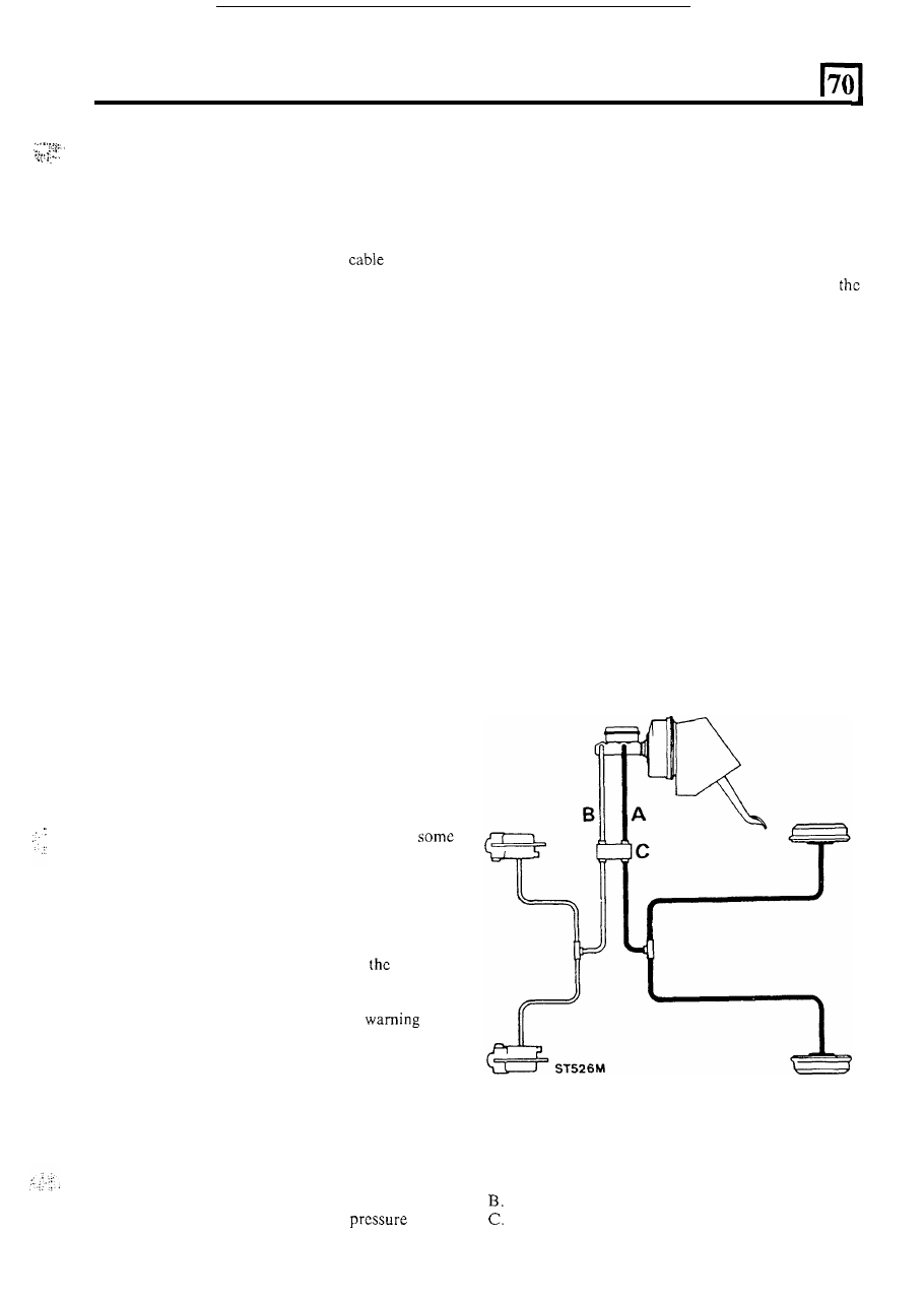
Land Rover 110 models have a Pressure Differential
Warning Actuator Valve (P.D.W.A. Valve) o r in
cases a combined P.D.W.A. Valve and a Pressure
Conscious Reducing Valve (P.C.R. Valve) situated
between the master cylinder and the front and rear
brakes.
The valves are bolted to the bulkhead within the engine
compartment. The type of valve fitted is dependent
upon the nature of the vehicle and
braking
classification regulations prevailing in the territory
where the ehicle is
to
operate. Both types
of valve
incorporate an electrical switch wired to a
bulb
on the vehicle control panel. The bulb will illuminate
momentarily when the starter motor is actuated
indicating that the brake warning circuit is functioning
correctly. A fault
in either the primary
or
secondary
circuits is evident
if the warning bulb illuminates upon
application
of the foot brake while the engine
is
running. Should a pressure failure occur
in the front
brake circuit (secondary) the piston in the P.D.W.A.
valve will
move in the diretion of the failed circuit
causing the switch to operate and the warning bulb to
illuminate. At the same time full fluid
in the
.
primary circuit to the rear brakes will continue. The
P.D.W.A. will function in a similar manner should a
failure occur in the primary, rear brake circuit. A
Girling type
80
vacuum servo is fitted when a
combination valve is used.
The
P.C.R. valve allows fluid to the rear brakes until a
predetermined pressure
is reached when the valve
closes. the valve, from this point on, will only permit a
proportion
of any increase in fluid pressure to reach
rear brakes to prevent premature locking of the rear
wheels. Should a failure occur in the front brake
secondary circuit the design
of the valve will ensure that
the fluid to
the rear brakes will by-pass the valve and
allow full circuit pressure to the rear wheel cylinder.
To
satisfy the demand
of
other regulations certain
vehicles are equipped with a deceleration actuated
anti-lock valve fitted in the rear brake (primary) line
instead
of a P.C.R. valve. Then this valve
is
used a
Girling type
80 vacuum servo is fitted. The valve is
situated on the inner face of the chassis right-hand side
member at
an angle of 20" to the horizontal
so
that the
angle
of inclination is towards the front of the vehicle.
Under normal braking conditions the valve remains
passive. When fierce or emergency braking is necessary
the valve operates at a pre-determined deceleration
figure and reduces the rate
of increase in the hydraulic
pressure to the wheel cylinders.
A. Primary circuit.
Secondary circuit.
P.D.W.A.
or
combination valve.
1