Defender 90 / 110 / 130. Manual - part 117
S
U
S
PENS
I
ON
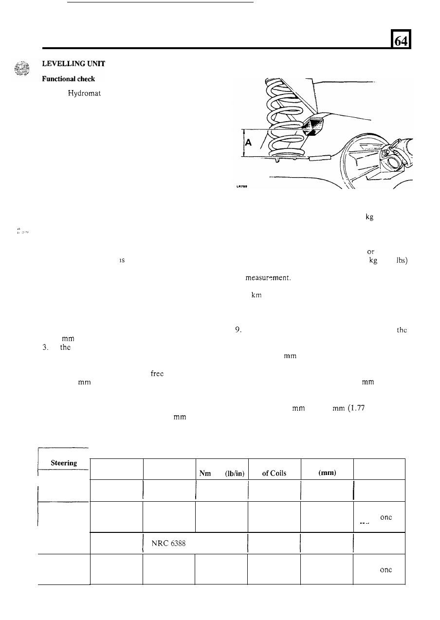
A Boge
levelling unit is located in the centre
of the rear axle.
When the vehicle is unladen the levelling unit has little
effect. The
unit is self-energising and hence the vehicle
has to be driven before the unit becomes effective, the
time taken for this to happen being dependant upon the
vehicle load, the speed at which it is driven and the
roughness of the terrain being crossed.
If
the vehicle
is
overloaded the unit will fail to level
fully and more frequent bump stop contact will be
noticed.
Should the vehicle be left for a lengthy period e.g.
overnight, in a laden condition, it may settle.
This
is
due to normal internal fluid movement in the unit and
is not detrimental to the unit performance.
Before carrying out the checks below, verify that the
vehicle is being operated within the specified maximum
loading capabilities.
If
the levelling unit is then believed
to be at fault, the procedure below should be followed.
Whilst slight oil seepage
permissible, the unit should
be renewed
if there is an excessive oil leak.
1. Remove excessive mud deposits from underneath
the vehicle and any heavy items from inside the
vehicle that are not part
of the original equipment.
2. Measure the clearance between the rear axle bump
pad and the bump stop rubber at the front outer
corner on both sides
of the vehicle, dimension
A .
The average clearance should be in excess
of
67
(2.8 in).
If
bump stop clearance is less than the above
figure remove the rear springs and check the free
length against the following data in the chart.
4. Renew any spnng where the
length is more
than 20
(0.787 in) shorter than the figures in
the chart.
5.
Having refitted
or renewed any springs repeat the
clearance check as described above. If the average
bump clearance is still less than 67
(2.8 in)
renew the levelling unit.
.
.
Steering
Side
R.H.
Part
Rate
Number
Free length
Colour
Number
Code
PASSENGER
R.H.
One Green
and
White stripe
NRC 7000
31.5
(180)
6
400
6. Load weights to the value
of 650
(1143 Ibs)
evenly over the rear load area of the vehicle and
leave it to settle undisturbed for minimum period
of thirty minutes.
7. With the driving seat occupied
with an
approximate equivalent weight of 75
(165
check the bump stop clearance and note the
8. Drive the vehicle on a test route approximately
5
(3 miles) in length over undulating roads or
graded tracks. At the completion of the drive bring
the vehicle to rest by light brake application
so as
not to disturb the vehicle loading.
Without disturbing the vehicle load and with
driving seat occupied, check the bump stop
clearance and note the reading, which must be in
excess of 45
(average).
10. Subtract the reading obtained under Instruction
7
from that obtained under Instruction 9. If the
change in clearance is in excess of
10
(0.394 in)
the levelling unit is functioning correctly.
11. If the figures obtained in instructions 9 and 10 do
not exceed
45
and
10
and 0.39 in)
respectively unload the vehicle and renew the
levelling unit.
PASSENGER
One Green
White stripe
NRC 7000
31.5
(180)
6
400
and
Two Blue
stripes
DRIVER
NRC 6388
31.5
(180)
6
412
Two Blue
stripes
DRIVER
131.5
(180)
6
412
15