Defender 90 / 110 / 130. Manual - part 115
SUSPENSION
750
16 Michelin
XS
750
x 16 Avon Rangers
750 x 16 (All others)
50.
Coat a joint washer both sides with sealing
compound and place in position on the lower
swivel pin.
51. Fit the lower pin with lip outboard.
Do
not secure
with bolts at this stage.
52.
Lubricate the Railko bush with an E P oil and fit the
top swivel pin with existing shims and fit the
securing bolts and jump hose bracket (do not
tighten).
53. Coat the threads of the lower swivel pin bolts with
Loctite 270 and fit, together with the brake disc
shield bracket, and tighten to
22 to 28
(16
to
21 Ibf
ft).
54. Tighten the top swivel pin securing bolts to 60 to
70
(44 to
52
Ibf ft).
55.
T o check the top swivel pin pre-load attach a spring
balance to the track-rod ball joint bore and pull the
balance
to
determine the effort required to turn the
swivel. The resistance, once
the initial inertia has
been overcome, should be
to
(8
to
10 Ibs). If necessary, adjust by removing
or adding
shims
to
the top swivel pin as required.
.
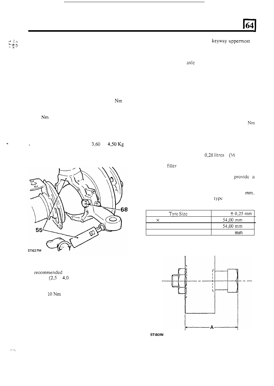
Dim ‘A’
51.00
63.
Fit the stub axle with the
at
12 o’clock. At this stage
it is most important to
ensure that the constant velocity joint bearing
journal engages fully into the bronze bush in the
rear of the stub
before the stub axle is secured
with bolts. Damage to the bush can occur if this
precaution is not observed. T o ensure proper
engagement, grasp the stub axle with one hand and
with the other pull the axle shaft into the bush. The
shaft and bush are correctly engaged when the end
of
the axle shaft splines are flush with the end of
the stub axle. This condition must be maintained
during all ensuing assembly operations.
64. Place the mud shield in position and secure the stub
axle to the swivel pin housing with the six bolts
using Loctite 270 and evenly tighten to 60 to
70
(44
to
52
Ibf ft).
65.
To
complete the reassembly, follow instructions 25
to 41 covering front hub overhaul.
66. Check that the swivel pin housing drain plug is
tightly fitted and remove the filler level
plug.
67. Inject approximately
pint) of
recommended
EP
oil until the
oil begins to run out
of the
hole. Fit and tighten the plug and wipe
away any
surplus oil.
68. Set
t h e
steering lock-stop bolts to
clearance between the tyre wall and radius arm
in
accordance with the dimensions below. This
dimension however, must bc set to 56
irrespective of tyre size and
where steering
gaiters are fitted.
56. Liberally apply
-
but do
not pack
-
a
grease between the lips of the swivel
oil seal
to
grams).
57.
Secure the
oil seal and joint washer with the
retaining plate and securing bolts tightening evenly
to 7 to
(5
to
7
Ibf ft).
58.
Fit the track-rod and drag link and secure with new
split pins.
59.
Fit the brake disc shield.
60. Loosely fit the lock stop bolt and nut
for later
adjustment
.
- -
Fit drive shaft and stub axle
61. Place a new joint washer in position on the swivel
pin housing to stub axle mating face.
62.
Taking care not to damage the axle shaft
oil seals,
insert
t h e
axle shaft, and when the differential
splines are engaged, push the assembly home.
7