Defender 90 / 110 / 130. Manual - part 121


  Index      Land Rover     Defender 90 / 110 / 130 - service repair manual


Search            


Content   ..  119  120  121  122   ..


Defender 90 / 110 / 130. Manual - part 121


BRAKING 

S

YSTEM 

Renewing secondary plunger seals 

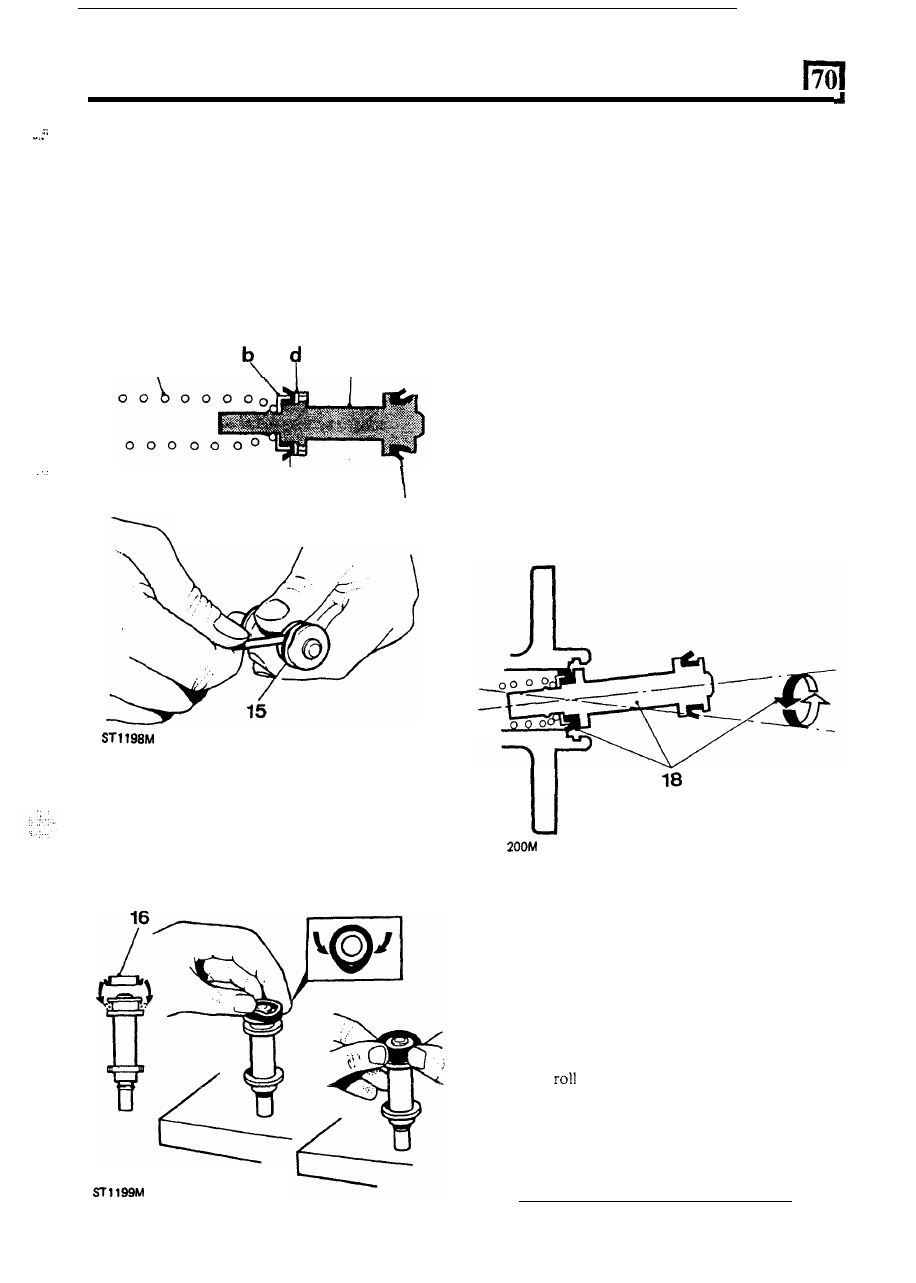
14.  Remove the following items from the plunger: 

,*: 

(a) spring 
(b) seal retainer 
(c) recuperating seal 
(d) washer 

outer seal. 

15.  Taking care not to damage the plunger prise off the 

14 

15 

16. 

Fit  a  new  outer  seal  using  the  same  procedure  as 
for the primary plunger outer seal by squeezing the 
seal between  the  finger  and  thumb into an  ellipse 
and press the raised  part 

of  the seal over the flange 

using the fingers 

of  the other hand. 

17. 

Fit  the  recuperating  seal  assembly  parts 

in  the 

reverse order 

of  removal. 

Assembling master cylinder 

It  is  important  that  the  following  instructions  are 
carried  out  precisely,  otherwise  damage  could  be 
caused to the new seals when inserting the plungers into 
the  cylinder  bore.  Generous  amounts  of  new  brake 

fluid  should  be  used 

to  lubricate  the  parts  during 

assembly.  Never  use  old  fluid  or  any  other  form 

of 

cleaning 

and 

lubricating 

material. 

Cleanliness 

throughout is essential. 

18. 

Clamp  the  cylinder  in  a  vice  and  lubricate  the 

secondary  plunger  seals  and  cylinder  bore.  Offer 
the  plunger  assembly  to  the  cylinder  until  the 
recuperation  seal 

is  resting centrally  in  the mouth 

of  the  bore.  Gently  introduce  the plunger  with  a 
circular  rocking  motion,  as  illustrated.  Whilst 
ensuring  that  the  seal  does  not  become  trapped, 

ease  the  seal  into  the  bore  and  slowly  push  the 
plunger down in one continuous movement. 

ST 

19. 

20. 

21. 

22. 

23. 

24. 

Fit  the  primary  plunger  assembly  using  the  same 
method  as  for  the  secondary  plunger.  Press  the 
plunger  down  and  secure  the  assembly  with  the 
plastic circlip. 
Slowly press the plunger  down the bore and fit the 

secondary plunger stop-pin. 
Lubricate new seals and 

fit to the inlet ports (large 

diameter downwards). 
Press  the  reservoir  into  position  and  secure  with 
the 

two 

pins. 

Fit a new washer to the reservoir cap and press the 
plastic baffle into position inside the cap. 
Fit a new  rubber seal to the cylinder  flange and fit 
the  master  cylinder  to  the  servo  and  secure  with 
two nuts and spring washers. 

13 

BRAKING 

SYSTEM 

Incorrect linings.  Badly lined shoes. Distorted 

shoes. Overloaded vehicle. Excessive 
braking.  Old hydraulic fluid. 

BRAKING SYSTEM 

FAULT DIAGNOSIS 

Replace the shoes, decrease vehicle load or 

hydraulic fluid 

as necessary. 

FAULT 

CAUSE 

ACTION 

Air in system. Badly lined 

Shoes 

distorted or incorrectly set. Faulty drums. 
Weak master cylinder mounting. 

FADE 

Check for air 

in 

the system using Hose Clamp 

and bleed if necessary. Check 

t h e  

master 

cylinder mounting, lined shoes and drums 
and replace as necessary. 

hydraulic 

fluid 

Brakes maladjusted. No clearance at master 
cylinder push rod. Seals swollen. Siezed pistons. 
Shoe springs weak 

or 

broken. 

faulty. 

SPONGY PEDAL 

Check the brake adjustment.  Check for clearance 
at the master cylinder, 

pistons 

or 

weak 

shoe springs. Repair or replace parts 

as necessary. 

HARD 
POOR BRAKING 

BRAKES PULLING 

FALL IN FLUID LEVEL 

LONG PEDAL 

Incorrect linings.  Glazed linings. Linings wet, 
greasy or not bedded correctly. 
unit inoperative.  Siezed caliper pistons. 
Worn shock aborbers causing wheel bounce. 

Siezed pistons.  Variation  in linings. Unsuitable 
tyres or pressures.  Worn shock absorbers. 
Loose brakes.  Greasy linings. Faulty drums, 
suspension  or steering. Contaminated seals. 

Replace the shoes, or if glazed, lightly rub down 

with rough sandpaper. Check caliper for damage 
and repair as necessary. Check servo. 
Fit new shock absorbers. 

Check 

tyres and pressures, seized pistons, 

greasy linings, 

or 

loose brakes; then check 

suspension, steering and drums. Repair 
or replace as necessary. Fit new shock 
absorbers. 

contamination, fit new seals 

and hoses. 

the pads for 

and for hydraulic fluid 

Worn disc pads. External 

Leak in Scrvo 

A.  Disc Brakes 

Discs running out 
pushing pads back. 
Misplaced dust covers. 

Drum Brakes 

Brakes need adjustment. 
Fluid leak. 
Fluid contamination. Wom or swollen seals 
in 

master 

Blocked filler 

vent. 

UNEVEN OR EXCESSIVE 
PAD WEAR 

A.  Check the disc run out does  not exceed 

(0.004 

in) 

1. 

Rotate the disc 

on the hub. 

2. Check the 

mounting faces. 

and for fluid leaks. Adjust brakes, repair leak, 
if 

necessary, or renew seals and change fluid. 

Check the brake adjustment, filler cap vent 

Disc corroded (by salt). Disc badly scored. Pads 
scored. Pads require interchanging.  Incorrect 
friction material. 

Check the disc for corrosion. 

or 

scoring and 

replace if necessary. Alternatively, interchange 
pads. Fit new pads with correct friction material. 

BRAKES BINDING 

leakage. 

DISC BRAKE 
PAD RATTLE 

Worn retaining pins. Worn discs. 

Renew the retaining pins, or discs. Apply disc 

brake lubricant to back 

of  pads. 

14 

... 

... 

. . 

... 

76 

C

HASSIS AND BODY 


Content   ..  119  120  121  122   ..