Defender 90 / 110 / 130. Manual - part 99
REAR DIFFERENTIAL
-
ONE TEN
109. Prevent the drive pinion from rotating and check
the
crown wheel backlash which must be
to
(0.006 to 0.011 in). If the backlash is not
within the specified limits, repeat the differential
backlash checks, instructions 96 to 102 looking for
possible errors.
Fit the differential cover and new gasket, coating
both sides of the gasket with Hylomar PL 32M or
an equivalent non-setting sealant.
Torque load for fixings is
to
kgf
(20 to
25 Ibf ft).
Reverse instructions
3
to
5 and coat t h e threads
of
the hub driving member bolts with Loctite
‘Studlock’ grade CVX and fit and tighten the bolts
evenly. Torque:
kgf
m
(73 Ibf ft).
112. Fit the rear axle assembly to
the vehicle.
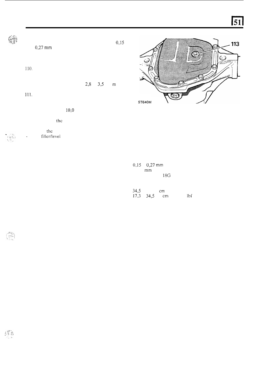
113. Replenish
differential lubricating oil, (see
Lubrication chart). After the initial axle run,
check
oil level and replenish as necessary to
114. Where major running parts have been replaced
during servicing,
it
is a recommended practice to
allow
t h e
axle assembly to ‘run in’ by avoiding,
where possible, heavy loads and high speeds
the
plug hole.
during initial running.
DATA
Crown wheel backlash .........................................
Differential bearings pre-load ................................
Pinion height setting
............................................
to
(0.006 toO.O1l in)
0,127
(0.005 in)
Set using gauge
191 P or
18G 191-4
Torque resistance initial setting figures
Torque to turn drive pinion and new pinion bearings
...
Torque
to
tum
drive pinion re-using the original bearings
.
to 46 kgf
(30
to
40
Ibf in)
to
kgf
(15
to
30
in)
15