Defender 90 / 110 / 130. Manual - part 98


  Index      Land Rover     Defender 90 / 110 / 130 - service repair manual


Search            


Content   ..  96  97  98  99   ..


Defender 90 / 110 / 130. Manual - part 98


REAR DIFFERENTIAL 

ONE 

TEN 

61.  Add 0,127 

(0.005 in), for bearing pre-load, to 

the  total  noted 

in  the  preceding  instruction.  ‘The 

sum  is  then  equal  to  the  nominal  value  of  shims 
required for the differential bearings: 
Shims  are 

in  the  range 

(0.003 in), 

(0.005 in), 

(0.010 in) and 

(0.030 in). 

the total 

value 

of 

shims required. 

62.  Remove  t h e   differential  unit  and  bearings  and 

place  aside. 

Do 

not  fit the shim washers  until 

subsequent  ‘Differential  backlash’  checks  have 
been made, instructions 96 to 

102. 

Fit 

drive pinion 

63.  Select shim washers 

of the same thickness 

as 

those  removed  from  under  the  pinion  inner  cup, 
instruction 

35, and place ready for fitting. 

64.  Position  the 

bearing 

detail  2,  and 

outer  bearing  cup  on  the  press 

tool 

1122. 

65.  Locate the assembly into the pinion  housing nose. 

’.. 

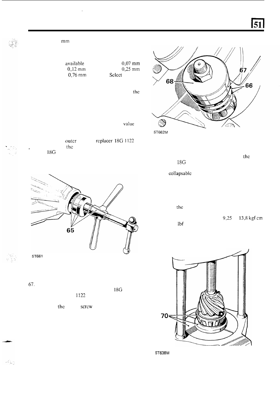
66.  Place  the  selected  shim  washcrs  on  to  the  inner 

bearing 

cup seating. 

Position  t h e  

inner 

bearing cup in 

the 

casing. 

68.  Position  the  inner  bcaring  replaccr 

1122 G 

detail  1, onto 18G 

and secure with  the fixing 

nut. 

69.  Hold  still 

centre 

and  turn  the  butterfly 

lever to draw 

in the bearing cups. 

70.  Press  the  inner  bearing  cone  onto 

drive 

71.  Position the pinion  and bearing 

in the casing; omit 

72. 

Fit the outer bearing cone onto the pinion. 

73. 

Fit  the  coupling  flange  and  plain  washcr  and 
loosely 

fit 

the flange nut. 

74.  Tighten  the  coupling  flange  locknut  to  remove 

end-float from the pinion. 

75.  Rotate 

pinion to settle the bearings and slowly 

tighten  the flangc locknut. Use a spring balancc 

to 

obtain  a  torque  resistance  of 

to 

(8 to 12 

in) to rotate 

t h e  

pinion. 

pinion. 

47 

B K ,  details 1 and 

2 and press 47. 

the 

spacer at this stage. 

continued 

11 

REAR 

DIFFERENTIA

ON

E TEN 

Drive pinion markings 

76.  Check  that  the  serial  number  marked  on  the 

pinion  end  face  matches  that  marked  on  the 
crown wheel, 

77.  The  markings  on  the  end  face  adjacent  to  the 

serial  number  are  of  no  significance  during 
servicing. 

78.  The figure marked on the end face opposite to the 

serial number indicates, 

in thousandths of an inch, 

the  deviation  from  nominal  required  to correctly 
set the pinion. A  pinion  marked plus  (+) must be 

set below nominal, a minus (-) pinion must  be set 
above nominal.  An  unmarked  pinion  must  be 

set 

at nominal. 

Drive pinion adjustment 

Ensure  that  the  pinion  end  face  is  free 

of  raised 

burrs around the etched markings. 

81.  Remove the  keep disc  from  the 

of  dial gauge tool 

191. 

82.  Place  the dial  gauge and  setting gauge 

191 P 

or 

191-4  on  a  flat  surface  and  zero  the  dial 

gauge stylus on to the setting gauge. 
Position the dial gauge centrally on the pinion  end 
facc with  the stylus registering on the lowest point 

on  one  differential  bearing  bore.  Note  the  dial 
gauge deviation from  the zeroed setting. 
Repeat  on  the other  bearing  bore.  Add  together 
the  readings,  then  halve  the  sum  to  obtain  the 
mean  reading.  Note whether the stylus has moved 

up or down from the zeroed setting. 

88 

79.  The  nominal  setting dimension  is  represented  by 

the  setting gauge  block 

191 

or  18G  191-4, 

which  is  referenced  from  the  pinion 

face  to 

the bottom radius 

of  the differential bearing bore. 

The 

latter 

gauge 

is 

illustrated 

following 

instruction 

Example 1 

obtained 

sidc 

Reading obtained R . H .  side 

0.006 in 

0.003 

in 

Add 

in 

0.003 

in 

i n  

0.003 

0.0015 

in 

Divide 

b y 2  

Therefore subtract 0.0015 in  from the shim thickness 

behind the pinion inner bearing track. 

Example 

Reading obtained 

L.H. side 

0.006 in 

Reading 

side 

Add 

0.006 

in 

in 

0.002 

in 

0.002 

b y 2  

in 

continued 

12 

REAR DIFFERENTIAL - 

ONE 

TEN 

t h e  

stylus has  moved  down, the amount is 

... 

., 

equivalent to the  thickness of  shims  that  must  be 
removed  from  under the pinion  inner cup to bring 
t h e  

pinion  down to the nominal position. 

t h e  

has 

up,  the  amount  is 

equivalent  to  the  additional  thickness  of  shims 
required  to  bring  the  pinion  up  to  the  nominal 
position. 

.., 

I -  

Illustration A. 

Using setting gauge 

191 P. 

Illustration 

Using universal setting block 

18G 191-4 

The  setting  block  has 

setting  heights  as 

follows: 
39.50 

Rationalised axle 

38.10 

Pre-Rationalised axle 

30.93 

Salisbury axle 

Ensure  that  the  height  marked 

30.93 

is  used  for 

this differential. 

E3 

86. 

Before  adjusting  the  shim  thickness, 

the 

pinion  face marking and 

if it has a plus (+) figure, 

subtract  that  amount 

in  thousands  of  inch  from 

the shim thickness figure obtained 

in the previous 

instruction.  Alternatively 

if the pinion has 

a minus 

(-) figure, add  t h e  amount to the shim  thickness 

figure. 

87.  Adjust  the shim  thickness  under  the pinion  inner 

cup  as  necessary,  by  the  amount  determined 

in 

instructions 

and 

86. 

88.  Recheck  the  pinion  height  setting instructions 82 

to 84. 

If t h e  setting is correct, 

mean reading on 

the  dial  gauge  will  agree  with  the  figure  marked 
on the pinion  end face.  For example, with  an end 

face marking of 

+3, the dial gauge reading should 

that the pinion  is 0.003 

in 

below nominal. 

89.  When 

the 

pinion 

setting 

is 

satisfactory, 

temporarily  remove t h e  pinion outer bearing. 

89 

90.  Fit  a  new  collapsable  bcaring 

flared  end 

outward,  to  the  drive  pinion  and  refit  the  outer 

bearing. 
Fit 

pinion oil 

91 

Fit the 

oil 

seal gasket. 

13 

REAR DIFFERENTIAL 

ONE TEN 

93.  Fit  the  pinion 

oil  seal,  lipped  side  first,  using 

general  purpose  grease 

or,  where  available,  a 

molybdenum  disulphide based  grease 

on  the  seal 

lip, using R O  1008 to drift 

in the seal. 

94. 

Fit 

the  coupling  flange  and  plain  washer  and 

loosely  fit  a  new  flange  nut.  Secure 

1205 to 

the coupling flange, using slave fixings. 

95.  Alternately  tighten  the  flange  nut  and  check 

drive  pinion  resistance  to  rotation  until  the 
following figures arc achieved, as applicable: 

re-using original pinion  bearings: 

to 

kgf 

(15 to 30 Ibf in). 

with  new  pinion  bearings: 

to 

kgf 

(30 to 40  Ibf  in). 

NOTE:  Once  the  bearing  spacer  has  started 

to 

collapse  the  torque  resistance  build-up  is  rapid, 
therefore check frequently,  using a spring balance, 
to  ensure  the  correct  figures  are  not  exceeded, 
otherwise a new collapsable bearing spacer will  be 
required. 

Differential backlash checks 

96.  Pick  up  the  differential  unit  as 

after 

instruction 

52. 

97.  Fit  the  differential 

u n i t  

and  lever  the  unit  away 

from  the  drive  pinion  until 

t h e  

opposite  bearing 

cup  is  seated  against  the  housing.  Do not  tilt 

unit. 

98.  Install  a  dial  gauge  on  the  casing 

with 

its  stylus 

resting 

on the back  face of  the crown wheel. 

the gauge. 

99.  Lever  the  differential  unit 

to  engage  the  crown 

wheel  teeth  in  full  mesh  with  the  drive  pinion 

teeth. 

t h e  

unit. 

100.  Note the total reading obtained on the dial gauge. 
101.  From  this  figure  subtract 

(0.010 in)  to 

obtain  the  correct  crown  wheel  backlash  w h e n  
fitted. The result  indicates  the value  of  shimming 
to be  fitted between  the differential case  and  the 
bearing  cone  at  the  crown  wheel  side  of  the 
differential. 

14 

102. 

Fit 

the shim  value  determined  in  instruction  101, 

taking 

the 

shims  from  the  pack  previously 

determined 

during 

‘Differential 

bearing 

adjustment’  checks,  instructions  57  to 

47  BL details 

I  and 2, 

134 DP. 

103.  Fit  the  remaining  shims  from  instruction 

to 

the 

opposite  side  o f   the  differential. 

18G 47  BL 

details 1 and 2, press 47, 

134 

DP. 

104. 

Fit 

differential unit with shims and bearings to 

the axle casing, using t h e  axle 

131 

with pegs 

131 F. 

105.  Remove the axle spreader. 
106. 

Fit  the  bearing  caps 

in 

their  correct  position, 

referring  to the relationship markings on  the caps 
and on the axle casing. 

107.  Tighten  the  bearing  caps  fixings  to 

to 

kgf 

(93 to 105 Ibf 

ft). 

108.  Mount  a  dial  gauge  on  the  axle  casing  with  the 

stylus 

o n  

a crown wheel tooth. 

continued 


Content   ..  96  97  98  99   ..