Defender 90 / 110 / 130. Manual - part 97


  Index      Land Rover     Defender 90 / 110 / 130 - service repair manual


Search            


Content   ..  95  96  97  98   ..


Defender 90 / 110 / 130. Manual - part 97


REAR 

DIFFERENTIAL 

ONE 

TEN 

... 

... 

,.. 

...... 

.., 

OVERHAUL 

REAR 

AXLE 

DIFFERENTIAL 

ASSEMBLY (SALISBURY) LAND ROVER  ONE TEN 
MODELS 

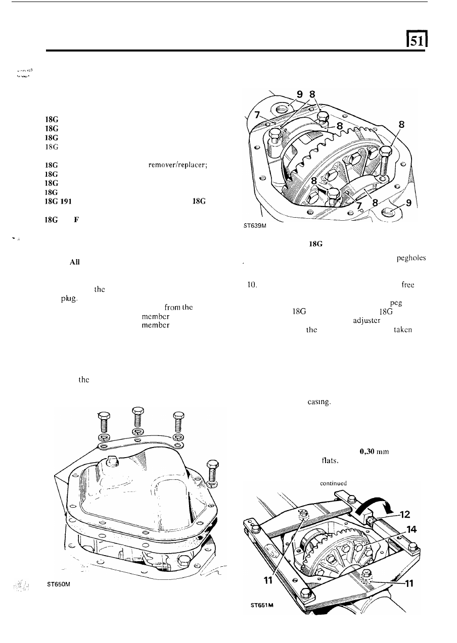
8.  Remove the fixings and withdraw  the differential 

bearing caps. 

Service tools: 
47 

screw press; 

131 

C axle spreader 

or axle compressor GKN  131; 

191 

dial gauge, bracket and base; 

1122 

screw press; 

1205 spanner for drive coupling; 

123 A pinion bearing cup remover; 

47 

BK  pinion  bearing cone 

47 

BL differential bearing remover; 

1122 

G pinion bearing cup replacer; 

134 

DP differential bearing replacer; 

setting gauge 

for pinion  height 

or 

191-4 

universal setting block; 

131 

pegs for axle spreader; 

RO 1008 oil seal replacer 

DISMANTLE 

NOTE: 

fixing bolts used 

on the differential assembly 

and differential cover have metric threads. 

1. 

Drain  off 

differential  lubricating  oil, and  refit 

2.  Remove the rear axle assembly 

vehicle. 

3 .   Remove the hub driving 

fixings. 

4.  Withdraw  the  driving 

and  axle  shaft 

sufficiently to disengage the differential. 

5 .  

Repeat instruction 4 for the other axle shaft. 

6.  Remove  the  fixings  and  support  strip  at  the 

differential  cover  and  withdraw  the  cover  and 

joint washcr. 

7. 

Note 

relationship marking on the bearing caps 

and axle casing to ensure correct refitting. 

Using axle spreader 

131 

9.  Clean out and examine the spreader tool 

provided 

in  the gear  casing face; ensure  that  the 

holes are free from dirt and burrs and damage. 
Ensure  that  the  turnbuckle  adjuster 

is 

to 

turn. 

11.  Fit  the  axle  spreadcr  to  engage  the 

holes. 

Spreader 

131 

C, Adaptor pegs 

131 

F. 

12. 

Using  a  spanner,  turn 

t h e  

until  all  free 

play  between 

spreader and casing 

is 

up, 

denoted by  the adjuster becoming stiff to 

t u r n .  

13. 

Check  that  the  side  members of  the  spreader are 
clear of the casing. 

14. 

Stretch  the  casing,  rotating  the  adjuster  by  one 

flat  at  a  time,  until  the  differential  assembly  can 
be  levered  out. 

Do not lever against  the spreadcr; 

use  suitablc  packing  under  the  levers  to  avoid 
damage to the 

CAUTION:  To prevent  permanent  damage to  the 
gear  carrier  case,  it  must  not  be  over-stretched. 
Each  flat on the turnbuckle is numbered  to enable 

check  to  be  made  on  the  amount  turned.  The 

maximum stretch permitted is 

(0.012 

in), 

equivalent to three 

15.  Ease off the adjuster and remove 

t h e  

spreader 

REAR DIFFERENTIAL - 

ONE 

TEN 

Using axle compressor 

GKN 

131 

16.  Place  the  tool  on  to  t h e   differential  casing,  as 

illustrated,  with  t h e   weld  seam  uppermost. 
Ensure  that  the  plates  rest  squarely 

on  the 

differential  machined  surface  and  the  end  bars 
butt against the edges of the casing. 

17.  Tighten  the  adjusting nuts  by  hand  only, until 

all 

slack is taken up. 

18.  Continue  to  tighten  both  nuts  alternately  with 

spanner, one flat at a time, to a maximum of  three 
flats. 

19.  Carefully lever-out the differential assembly. 

Dismantle differential 

20.  Add  alignment 

marks 

between  the  crown 

and 

differential 

for 

purposes, 

then 

the  fixings  and  withdraw  the  crown 

wheel. 

24. 

Lift 

out the cross-shaft and pinions. 

25.  Withdraw 

four dished  thrust washers. 

26.  Withdraw 

the 

lower differential  wheel  and  thrust 

washer. 

continued 

20 

21.  Note  t h e   alignment  markings  on  the  two 

22.  Lift off the upper case. 
23.  Withdraw  the upper differentiai  wheei  and  thrust 

differential  casings 

to 

ensure  correct  refitting, 

then  remove the fixings. 

washer. 

22 

REAR DIFFERENTIAL - 

ONE TEN 

27.  Remove  the  differential  bearing  cones  using 

remover 

18G 47 

BL 

and  adaptors  1  and  2  and 

press 47. 

28.  Withdraw 

shim  washers  fitted  between  the 

bearing cones and the differential casings. 

34.  Withdraw 

t h e  

outer bearing cone. 

35.  Extract  the  pinion  inner  bearing  cup  and  shim 

washers  from  the  casing.  Note  t h e   shim  washer 
thickness. Remover 

123 A .  

36. 

Extract 

pinion  outer  bearing  cup  from  the 

casing. Remover 

123 

A .  

Remove final 

drive 

pinion 

29.  Prevent  the  coupling  flange  from  rotating  and 

remove  the  flange  locknut  and  plain  washer. 
Spanner 

30.  Support the drive pinion  and remove the coupling 

flange by  tapping 

with 

a hide hammer. 

31.  Withdraw the drive pinion together with  the inner 

bearing cone. 

32.  Withdraw  and  discard  the  collapsable  bearing 

spacer. 

33.  Withdraw the oil seal, gasket and oil thrower. 

.... 

... 

... 

.: 

... 

37.  Remove  the  inner  bearing  cone  from  the  pinion. 

Remover 

18G 47  R K  and Press 47. 

continued 

REAR DIFFERENTIAL- 

ONE 

T

EN 

INSPECTION 

38.  Examine  all  components  for  obvious  wear 

or 

damage. 

39.  The  bearing  cones  must  bc  a  press 

fit 

on 

locations,  except  the 

pinion  flange  and 

bearing which is a slide fit. 

40.  The  crown  wheel  and  pinion  are  supplied  as  a 

matched  pair  and  must  not  be  interchanged 
separately. 

new crown wheel  and pinion  matched  pair  may 

be fitted to an original  gear carrier casing 

i f  sound. 

The  original  crown  wheel  and  pinion,  if  sound, 

may be fitted into a replacement casing. 

41.  The  two  parts  of  the  differential  unit  casing  arc 

matched and must not be replaced separately. 

42.  Discard and renew all thrust washers. 
43.  Differential  housings  with  worn  thrust  washer 

seatings must be replaced as a pair. 

face  for  burrs  and  damage  which  could  lead  to 
crown wheel run-out when fitted. 

Examine the differential case to crown whecl joint 

ASSEMBLE 

55. 

Position  a  suitablc  dial  gauge  indicator  on  the 

casing with 

t h e  

stylus registering on  the back  face 

of the crown wheel. 

56.  Rotate  the  differcntial  and  chcck  the  total 

indicated 

run-out 

on  the  crown  wheel  back  facc. 

This  must  not  exceed 

If 

run-out  is  excessive,  check  the  mating  faces  for 

dirt and  damage; 

if 

select  a  new  radial 

position  for 

t h e  

crown  wheel. 

continue with 

following check. 

* -  

Assemble differential 

unit 

Differential  bearing adjustment 

45.  Fit  the differential lower wheel  and thrust washer 

to  the differcntial case.  Sec illustration  following 
instruction 23. 

46.  Fit the dished thrust washers. 
47.  Fit the cross-shaft and pinions. 
48.  Fit the differential upper wheel and thrust  washer. 

57.  Insert  two  levers  between  the  casing  and  the 

differential 

u n i t  

at 

side. 

58. 

the differcntial  unit  fully 

to 

one side of  the 

casing; do not 

tilt 

the unit. 

59.  Rotate  the differential  unit  to 

the bearings, 

to lever the differential  to  the side, then 

60.  Lever 

the 

assembly  fully  to the other side 

of 

casing, rotate  the 

unit  to 

settle the bearings,  then 

note 

t h e  

total indicator reading. 

49.  Fit the differcntial upper case lining-up the marks. 

zero 

dial gauge indicator. 

50.  Secure  the  assembly 

with 

bolts  using  Loctite 

'Studlock'  grade 

CVX on  the 

and  tighten 

evenly  and  diametrically  to 

to 

kgf 

m  (66 

to 75 Ibf 

f t ) .  

51.  Fit 

crown wheel  to the differcntial  casing. Use 

Loctite  'Studlock' 

CVX  on  the  fixing  bolt 

threads  and  tighten 

to 

13 

to 

kgf  m  (95  to 

105 Ibf 

f t ) .  

52.  Prcss on 

t h e  

differential  roller  bearing cones  less 

shim  washers,  using 

134 

DP,  and  leave 

t o  

one side until required for instruction  96. 

continued 

53.  Fit the bearing cups to the differential. 
54. 

Fit  the  differential 

and  bearings  to  the  gear 

carrier  casing,  and  rotate  unit 

centralize  the 

bearings. 

Do not fit the bearing caps. 

10 


Content   ..  95  96  97  98   ..