Defender 90 / 110 / 130. Manual - part 95


  Index      Land Rover     Defender 90 / 110 / 130 - service repair manual


Search            


Content   ..  93  94  95  96   ..


Defender 90 / 110 / 130. Manual - part 95


PRO

PELLER S

HAFTS 

OVERHAUL PROPELLER SHAFTS 
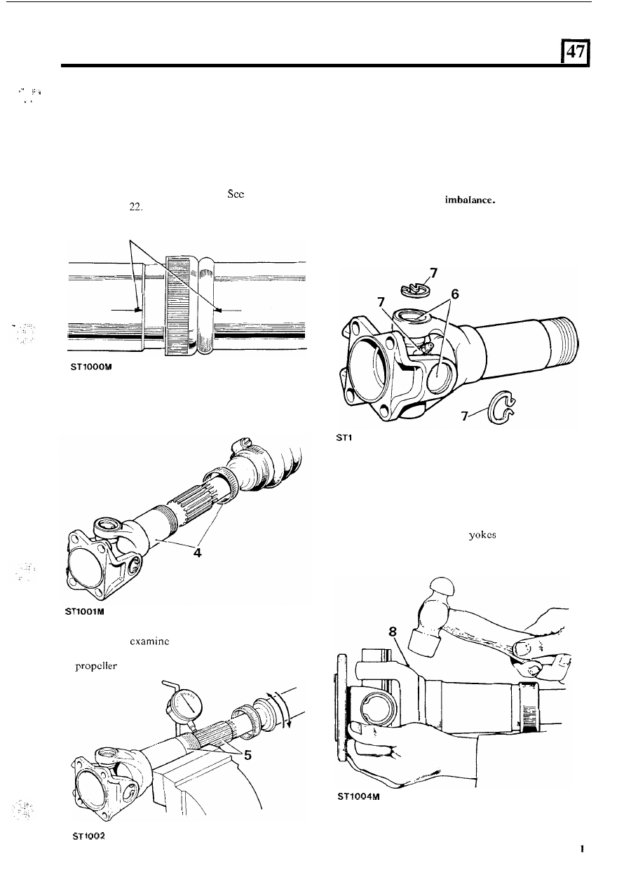
Dismantle 

1.  Remove the propeller shaft from the vehicle 

2.  If  a  gaiter encloses  the sliding member release  the 

two  securing clips.  Slide t h e  gaiter along  the  shaft 
to expose the sliding member. 

3.  Note  the  alignment  markings  on  the  sliding 

member and the propeller shaft. 

note following 

instruction 

4.  Unscrew 

the 

dust  cap  and  withdraw  the  sliding 

member. 

5 .  

Clean  and 

the  splines 

for  wear.  Worn 

splines 

or  excessive  back-lash  will  necessitate 

shaft renewal. 

6. 

Remove  paint,  rust,  etc.  from  the  vicinity 

of  the 

universal joint bearing cups and circlips. 

NOTE:  Before  dismantling  the  propeller  shaft  joint, 
mark the position of the spider pin lubricator relative to 
the journal  yoke  ears  to  ensure  that  the  grease  nipple 
boss  is  re-assembled  in  the  correct  running position 

to 

reduce the possibility of 

7. 

Remove the circlips, and grease nipple. 

00 

3 M 

8. 

Tap the yokes to eject the bearing cups. 

9.  Withdraw the bearing cups and spider and discard. 

10.  Repeat  instructions 

to 

8  at  opposite  end  of 

11. 

Thoroughly  clean  the 

and  bearing  cup 

propeller shaft. 

locations. 

Assemble 

12.  Remove the bearing cups from the new spider. 
13.  Check  that  all  needle  rollers  are  present  and  are 

properly positioned  in the bearing cups. 

14.  Ensure  bearing  cups  are  one  third  full  of  fresh 

lubricant. See Lubrication chart. 

15.  Enter the  new  spider complete with  seals into the 

yokes  of  the  sliding  member  flange.  Ensure  that 
the grease 

hole faces away from the flange. 

16. 

Partially  insert  one bearing  cup into  a  flange  yoke 

and  enter the  spider trunnion  into the bearing  cup 
taking care not to dislodge the needle rollers. 

17.  Insert  the  opposite  bearing  cup  into  the  flange 

yoke.  Using  a  vice,  carefully  press  both  cups  into 
place  taking  care  to  engage  the  spider  trunnion 
without dislodging the needle rollers. 

18.  Remove the flange and spider from the vice. 
19.  Using  a  flat  faced  adaptor 

of 

slightly  smaller 

its respective  yoke  until  they  reach  the  lower  land 
of  the  circlip  grooves. 

Do  not  press  the  bearing 

cups below  this point  or damage may be caused  to 
the cups and seals. 

diameter than  the bearing cups press each cup into 

PROPELLER SHAFTS 

20.  Fit the circlips. 
21.  Engage  the  spider  i n   the  yokes  of  the  sliding 

member.  Fit  the  bearing  cups  and  circlips  as 
described in instructions 

15 to 20. 

22.  Lubricate  the  sliding  member  spines  and 

fit  the 

sliding member to the propeller shaft ensuring that 
the  markings  on  both  the  sliding  member  and 
propeller shaft align. 

NOTE.  The Universal joints  on  the  front propeller 

shaft are, by  design,  not assembled in-line with one 
another. Nevertheless,  the  alignment marks  on  the 
sliding  member  and  propeller  shaft  must  coincide 

when assembling. 

23.  Fit and tighten the dust cap. 

Fit  the  grease nipples to  the  spider and  the  sliding 

member and lubricate. 

25.  Slide the gaiter (if fitted) over the sliding member. 
26.  Locate  the  sliding  member  in  the  mid-position  of 

its travel  and  secure the gaiter clips.  Note  that  the 
gaiter clips must be positioned  at 

180" to each other 

so  that  they  will  not  influence  propeller  shaft 
balance. 

26 

ST 

27.  Apply  instructions 

15 to 20 to  the opposite  end of 

28. 

Fit the grease nipple and lubricate. 

29.  Fit 

propeller shaft to the vehicle. 

the propeller shaft. 

REAR DIFFERENTIAL - 

NINETY HEAVY DUTY 

OVERHAUL  REAR  AXLE  DIFFERENTIAL 

7.  Remove  the  split  pin  securing  the  pinion  flange 

(option) 

8.  Remove  the  pinion  flange  n u t   using  service  tool 

Service tools: 

1205 flange holder tool; 
191 pinion height setting gauge; 

191-4 universal setting 

47-6 pinion head bearing 

1382 

oil seal replacer; 

RO 

extractor for pinion bearing caps; 

RO 

262757-1 replacer - use with 

RO 

RO  262757-2 adaptor tail bearing cap replacer; 
RO 530105  spanner 

differential  flange  and  carrier 

bearing nuts; 
RO 530106 bracket for dial gauge and indicator; 
MS 47 press 

ASSEMBLY 

Land  Rover  Ninety  Heavy  Duty 

nut. 

1205, to 

the flange. 

DISMANTLE 

is  essential  that  differential  components are marked 

in  their  original  positions  and  relative  to  other 

components 

so  that,  if  refitted,  their  initial  setting  is 

maintained.  Note  that  the  bearing  caps  must  not  be 
interchanged. 

1. 

Remove the differential assembly from the axle. 

2.  Drift  out  the  roll  pin  securing  the  bearing  nut 

locking  fingers  to  the  bearing  caps.  Remove  the 
locking fingers. 

3. 

Slacken the bcaring cap bolts and mark t h e  caps for 
reassembly. 

4. 

Using service tool  R O  

remove the bearing 

adjusting nuts. 

5.  Remove the bearing cap bolts and bearing caps. 

6. 

Lift  out  the  crown  wheel,  differential  unit  and 

bearings. 

9.  Withdraw  the  pinion  complete  with  pinion  head 

bearing  and  outer  bearing  shims.  Withdraw  the 

shims. 

10.  Remove  the  pinion  flange  oil  seal,  spacer  and 

bcaring. Discard the oil seal. 

11.  Using service tool R O  

the pinion 

head bearing track and shim and drift out the outer 
bearing track from the differential housing. 

continucd 

REAR DIFFERENTIAL - 

NINETY 

HEAVY 

DUTY 

18.  Dismantle  the  pinions  and  crosspin  assembly, 

noting the relevant positions 

of 

all 

components. 

19.  If  required,  extract  the 

bearings  and  place 

them 

in 

relative outer tracks. 

12.  Remove the  pinion  head  bearing with  service tool 

13. 

For 

purposes,  add  alignment  marks 

to 

MS 47 and adaptor 18G 

the crown wheel and differcntial case halves. 

INSPECTING 

WARNING: 

avoid  personal  injury,  the  differential 

assembly must be very securely retained while removing 
the bolts from the crown  wheel  and case halves, 

as these 

damage. 

bolts are Loctited and may be difficult 

to remove. 

21. 

bearings  must 

press  fit,  except  the  flange 

end pinion  bearing, which must be a slide 

fit 

on 

the 

retaining fixture can be made from angle iron with 

shaft. 

and 

bolts  welded 

it, 

as illustrated, 

that 

when  the 

is  clamped  in 

a  vice,  the  differential 

matched  set  and  must 

not 

interchanged 

assembly can be  located  over the 

with  the  fixture 

separately. 

bolts between the case webs. 

23.  Bevel pinion housing and bearing caps are matched 

sets and must not be interchanged separately. 

14.  Remove the crown wheel. 

24.  The differcntial  case  halves are a  matched  set and 

Remove 

screws  holding 

t h e  

case  halves 

must  not  be  interchanged  separately.  New  screws 

for 

securing the case halves are already coated with 

16.  Withdraw the upper half of  the casing. 

a  dry  locking  compound 

and 

do  not  require  the 

17.  Withdraw the upper side gear. Note that there may 

application 

of  Loctite.  If 

t h e  

old 

screws are being 

reused, 

threads  must 

cleaned  and  coated 

with Loctite ‘Studlock’ just prior 

to assembly. 

together. 

be thrust washers fitted t o  the side gears. 


Content   ..  93  94  95  96   ..