Defender 90 / 110 / 130. Manual - part 100
REAR DIFFERENTIAL
-
NINETY
FRONT DIFFERENTIAL - NINETY AND ONE TEN
....
.
.
..
Drive pinion adjustment
45. Ensure that the pinion end face is free of raised
burrs around
etched markings.
46. Remove the keep disc from the magnetised base of
dial gauge tool
18G 191.
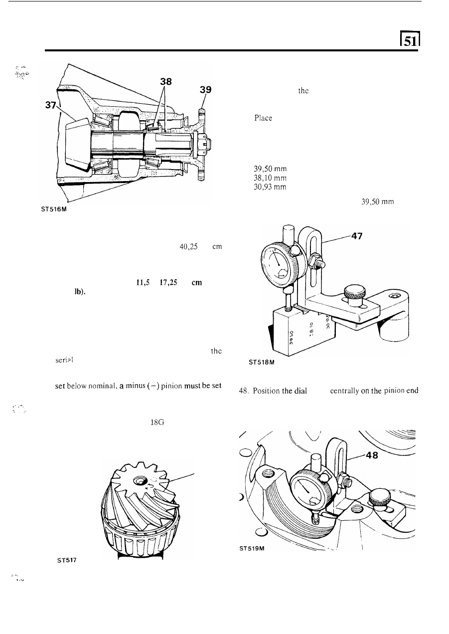
47.
the dial gauge and setting block on a flat
surface and zero the dial gauge stylus
on
the setting
block.
NOTE: The setting block has three setting heights
as follows:
Rationalised axle
Pre-Rationalised axle
Salisbury axle
Ensure that the height marked
is used
for this differential.
40.
Do
not fit the oil seal at this stage.
41. Tighten
t h e
pinion flange
n u t
slowly
until
the force
required to rotate the pinion is 23 to
kgf
(20 to 35 Ibf in). This will pre-load the bearings in
order to check the pinion height dimension.
NOTE: If using original bearings, which are bedded
in, the pre-load figure
is
to
kgf
(10 to
15 in
.
. I .
.
..
Drive pinion markings
42.
The markings on the end face adjacent to the serial
number are of no significance during servicing.
43.
The figure marked
on
t h e
end face opposite to
the deviation from nominal required to correctly
set the pinion. A pinion marked plus (+) must be
above nominal. An unmarked pinion must be set at
44. The nominal setting dimension is represented by
the setting gauge block
191-4 which is
referenced from t h e pinion end face to the bottom
radius
of the differential bearing bore.
number indicates, in thousandths of an inch,
gauge
face with the stylus registering on the lowest point
on one differential bearing bore. Note the dial
gauge deviation from the zeroed setting.
.
. . ,
nominal.
43
I
I
continued
.
..
.
.
.
19