Defender 90 / 110 / 130. Manual - part 80


  Index      Land Rover     Defender 90 / 110 / 130 - service repair manual


Search            


Content   ..  78  79  80  81   ..


Defender 90 / 110 / 130. Manual - part 80


LT95 FOUR SPEED GEARBOX 

6. 

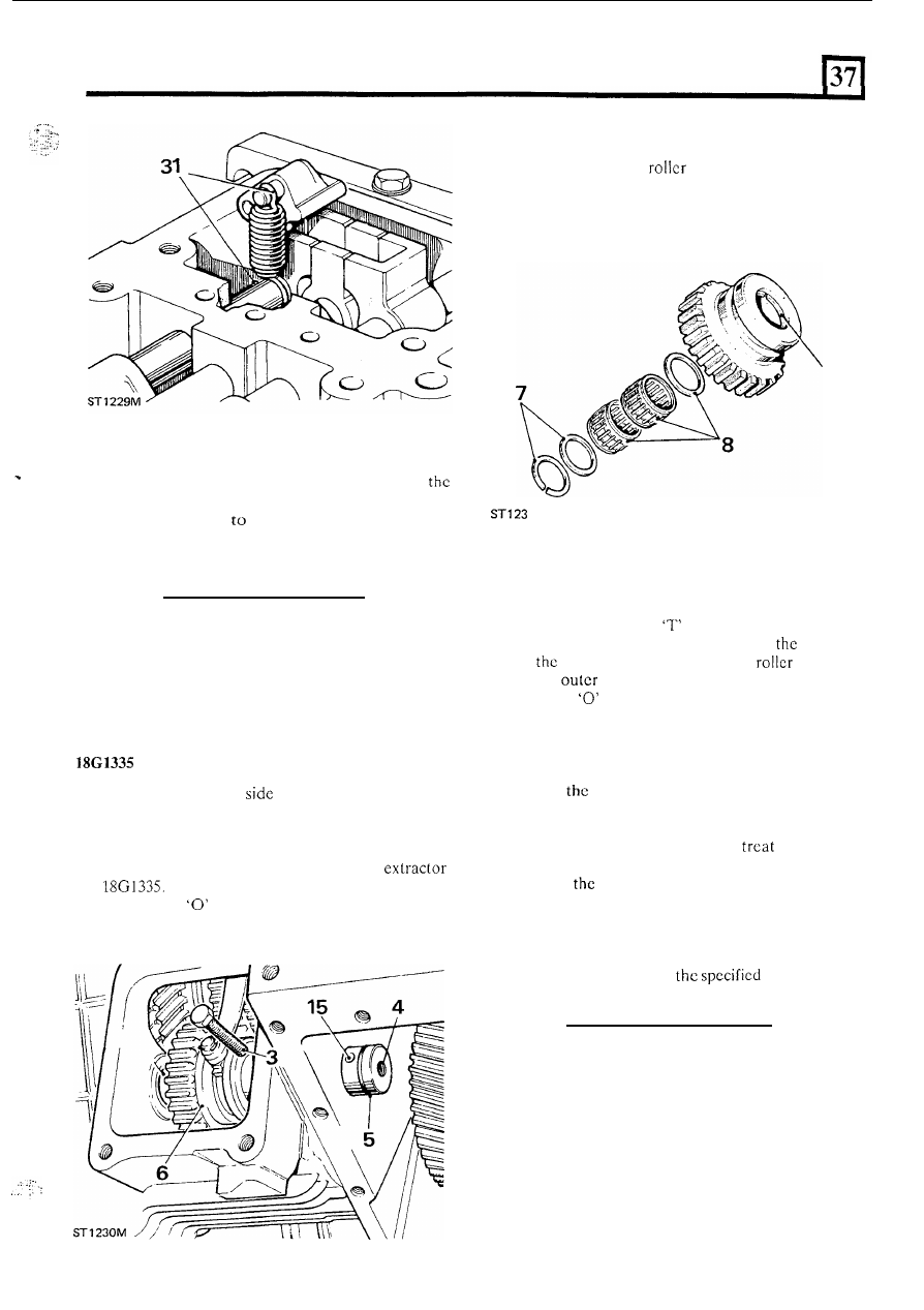
Lift out the reverse idler gear assembly. 

7.  Remove the circlip and plain washer. 

Lift out the needle 

bearings and further plain 

washer. 

9.  Withdraw the remaining circlip. 

32.  Fit the detent balls and springs. 
33.  Selcct neutral and  using a new joint  washer, 

fit 

gearbox  top cover and  secure with  the  eight  bolts, 
and evenly tighten 

the correct torque. 

34. 

Fit the reverse light switch 

35.  Fit the bell  housing. 

Assemble reverse idler gear and shaft 

REMOVE  AND  OVERHAUL  REVERSE  IDLEK 
GEAR AND SHAFT 

Special 

tool: 

extractor for shaft 

1. 

Remove the gearbox 

cover. 

2.  Remove the gearbox bottom cover. 
3.  Remove the bolt securing 

the 

idler gear shaft in 

t h e  

4.  Withdraw  the  idler  gcar  shaft,  using 

5 .  

Remove t h e  

ring seal. 

gearbox casing. 

10. 

If  removed,  fit  the  shaft  support  bush,  using 
Locquic primer grade 

and ‘AVV’ grade. 

11. 

Fit the circlip to selector groove end of 

gcar. 

12.  Fit 

plain washer and two needlc 

bearings. 

13. 

Fit the 

plain  washcr and secure with circlip. 

14. 

Fit a new 

ring seal to the idler gear shaft. 

15.  Offer  the  idler  shaft  to  the  gearbox  and  align  the 

16.  Smear clean gearbox oil onto 

the 

‘0’ 

ring seal. 

17.  Position the reverse idler assembly in the casing. 
18.  Engagc 

sclcctor 

foot in the idler gcar groove. 

19.  Drive in  the idler gear shaft until 

t h e  

retaining  bolt 

holes are aligned. 

20. 

Before  fitting  the  retaining  bolt, 

the  threads 

with  Locquic  primer  grade 

‘T’ and  allow  to  dry. 

Then, 

fit 

bolt  using Loctite Studlock grade. 

21.  Fit  the  gearbox  bottom  cover  using  a  new  joint 

washer  and  secure  with  the  fourteen  bolts  evenly 
tightening to the correct torque. 

22.  Using 

a new j o i n t  washer fit the side cover with the 

four bolts and tighten to 

torque. 

retaining bolt holes. 

49 

LT 95 FOUR SPEED GEARBOX 

REMOVE 

AND  OVERHAUL  FRONT  COVER  AND 

OIL PUMP 

Service tools: 

Centralising 

tool 

guide and 

assembly 

tool 

for 

fitting  oil  seal  and  oil 

feed ring. 

Lift  out the  retainer  staple from  the  clutch  release 
bearing  assembly  and  t h e  release  lever.  See clutch 

release overhaul. 

2.  Withdraw the release bearing assembly. 
3. 

Remove the slave cylinder 

4. 

Remove the spring clip. 

5 .   Withdraw the clutch release lever. 
6.  Remove  the  front  cover  assembly,  complete 

with 

oil pump joint washer. 

7.  Remove the shim washer located between  the front 

cover and 

layshaft front bearing. 

16.  Press  in  the  oil  feed  ring, using 

guide  and 

adaptor. 

17.  Fit  the ball,  spring and  plug. When  fitted, the plug 

must  be  flush  with, 

or  n o t   more  than 

in) below the f r o n t  cover rear face. 

Fit the oil pump ring gear. 

Overhaul 

8. 

9. 

12. 

13. 

Remove  the  pump  cover  gasket  and  oil  pump 

drive. 
Withdraw the oil pump ring gear. 
Remove the oil feed ring. 
Withdraw the oil seal. 
Remove the plug 

and 

withdraw  the ball  and spring 

from the relief valve  housing. 
If  required,  drift  off  t h e   extension  sleeve.  Fit 
repiacemenr  using 

275 grade. 

Reassemble 

14.  Press 

in  the oil  seal, plain  face  first,  using  186134 

guide and 

adaptor. 

15.  Align  the centre  hole  of  three  in  the  oil  feed  ring 

with 

the oil delivery hole in the front cover. 

LT 95 FOUR SPEED GEARBOX 

Fit cover assembly 

to 

gearbox 

19.  Position  the layshaft  bearing shim washer. 

20.  Position  t h e   front  cover  assembly  and  loosely  fit 

the fixings. 

21.  Fit  the  oil  pump  drive  gear  to  engage  the  drive 

square 

in 

the layshaft. 

22. 

Fit 

the oil  pump cover and joint washer  and 

fit 

the 

fixing screws and  washers  and  carefully  tighten  to 
the correct torque. 

23. 

Fit  the  gauge 

to  align  the  primary  pinion 

with 

the bell housing. 

Visually  check  that  the  front  cover  is  concentric 
about  the  primary  pinion.  Adjust  the  front  cover 

position about its fixings to suit. 

25.  When satisfactory, tighten the front cover fixings. 
26.  Fit the clutch release lever and spring clip. 
27.  Fit the slave cylinder push-rod. 

28.  Fit the release bearing assembly. 
29.  Fit  the retainer staple 

to the 

clutch  release bearing 

assembly and lever. 

REMOVE  AND  OVERHAUL  BEARING  PLATE 
ASSE 

MB 

Remove the bell  housing and position  the gearbox 

with 

the front end uppermost. 

2.  Remove the oil pump gears cover and joint washer. 
3.  Withdraw the 

pump drive gear. 

4. 

Temporarily  remove  the  four fixing studs from  the 
gearbox front face. 

Ease the bearing piate away from  the gearbox. 

6.  Withdraw  the  two  dowel  sleeves  which  locate  the 

bearing plate. 

7.  Withdraw  the  bearing  plate  assembly  complete 

with 

primary pinion and layshaft. 

Withdraw the joint washer. 

9.  Withdraw the layshaft. 

Assemble bearing plate assembly 

NOTE: To replace a bearing  plate,  a  bearing plate and 
gearbox casing mated assembly must be fitted. 

10. 

Locate  t h e   cone  i n t o   the 

Lubricate the oil tube, using clean gearbox oil. 

12. 

Position the joint washer. 

13. 

Engage  the  layshaft 

with 

the  primary  pinion  and 

front bearing outer member. 

14. 

Fit the bearing plate and layshaft. 

15.  Align  the bearing plate 

with 

the gearbox casing 

and 

slide home the dowel sleeves. 

16.  Refit  the  studs. 

Loctite  'Studlock'  grade 

CVX,  on 

t h e  

two  upper  studs  securing  threads 

before fitting. 

synchromesh unit. 

17.  Fit the oil pump drive gear. 
18.  Using  a  new  joint  washer 

fit 

the  oil  pump  gear 

19. 

Fit the bell housing. 

cover. 

51 

LT 95 FOUR SPEED GEARBOX 

REMOVE AND OVERHAUL PRIMARY PINION 

1.  Remove the bell housing. 

Remove the front cover and oil pump assembly. 

3.  Remove the bearing plate assembly. 
4. 

Remove the circlip. 

Lift off the shim washer. 

6.  Press out the primary pinion. 

240M 

7. 

Withdraw 

t h e  

bearing retaining plates and serrated 

8.  Press out the primary pinion bearing. 

bolts. 

Assemble primary 

pinion 

9.  Check that the orifice 

in the oil tube is clear. 

10.  During refitting,  take  care  to avoid damage to the 

oil  tube.  Rotate the shaft 

i n   the  bearing 

to  ensure 

that the oil tube is straight. 

11. 

Support  the  bearing  plate  using  suitable  wooden 
blocks.  Position  the  blocks  across  the  bearing 

housing aperture to act as assembly stops. 

12.  Press 

in  the  bearing  until  flush  with  the  bearing 

plate. 

13.  Press in the primary pinion. Check that the bearing 

remains flush 

with 

the bearing plate. 

14. 

Fit the retaining plates and serrated bolts. 

15. 

Fit the shim washer and circlip. 

16.  Measure the  clearance between  the  circlip  and  the 

shim  washer.  There  must  be  a  clearance  of 

in) maximum. 

17.  If  required,  adjust  the  clearance  by  fitting  a 

replacement  shim  washer.  Shim  range  is 

to 

(0.079 to 

in) 

in 

in) 

stages. 

18.  Fit the bearing plate assembly. 
19.  Fit the front cover and oil pump assembly. 

Fit 

the bell housing. 

52 


Content   ..  78  79  80  81   ..