Defender 90 / 110 / 130. Manual - part 81


  Index      Land Rover     Defender 90 / 110 / 130 - service repair manual


Search            


Content   ..  79  80  81  82   ..


Defender 90 / 110 / 130. Manual - part 81


LT 95 FOUR SPEED GEARBOX 

REMOVE  AND  OVERHAUL  THE  MAINSHAFT 

ASSEMBLY 

. . 

... 

Special tool: 

1861388 - extractor for mainshaft spacer and gear 

1.  Remove the bell  housing. 

Rcmove the front bearing plate. 

3. 

Remove the main gearchangc 

4. 

Removc  the  mainshaft  rear  bearing  housing  and 

5. 

Remove  the  bottom  cover  from  the  transfer 

roller bearing. 

gearbox. 

NOTE:  At  this  stage  in  the  dismantling,  on  early 
gearboxes only, it is necessary to remove the transfer top 

cover  selector  finger  and  shaft.  On  later  gearboxes  the 
cross-shaft  is  machined  to  enable  the  spacer  to  be 
completely  withdrawn.  Also  the  main  shaft spacer  and 
transfer  gear  are  secured  by  Loctite  275  to  the  main 

shaft. 

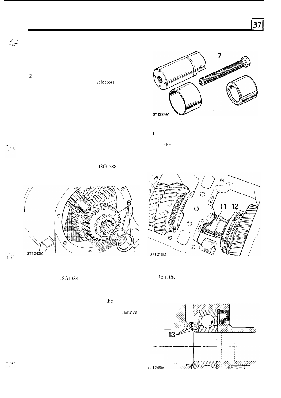
6.  Remove the snap-ring, shim  washer  and mainshaft 

transfer gear, using special tool 

7. 

Fit extractor 

to transfer gear spacer. 

8.  Withdraw  the spacer along the  mainshaft  until  the 

larger diameter 

on  the  spacer  reaches the  transfer 

gear lever cross-shaft. 

9.  Withdraw  the  spacer  through 

machined 

10. 

When  the  spacer is  free  on  the  mainshaft 

scollop. 

the 

extractor. 

Withdraw  the  mainshaft  assembly,  allowing  the 
first-speed  gear  to remain  behind  to  avoid  fouling 

on 

casing. 

12. 

Lift out the first-speed  gear. 

13. 

first-speed gear, scalloped thrust  washer, 

thrust  needle  bearing  and  stepped  thrust  washer, 

stepped face outwards. 

14.  Withdraw the mainshaft spacer. 

.  . 

53 

LT 

95 FOUR 

SPEED GEARBOX 

Overhaul mainshaft assembly 

Dismantle 

15. 

Withdraw 

first-speed  gear, thrust  washers  and 

roller bearings from the rear 

of  the shaft. 

16.  Remove  the  snap-ring  and  shim  washer  from 

front 

of  the shaft. 

17.  Lift 

off  the 

gears  synchromesh 

assembly. 

18.  Withdraw the third and second-speed gears and the 

associated 

thrust 

washers  and 

bearings. 

19.  Dismantle  the 

gears  synchromesh 

assembly, first  pushing  down  the  sliding blocks 

to 

free  the  synchromesh  balls  from  the  retaining 
groove in the outer member. 

29 

Assemble 

22.  Replacement  thrust  washers  and  roller  bcarings 

must not be degreased. 

Lubricate  all  items  before  assembly, 

clcan 

main gearbox oil. 

24.  Fit the oil seal to 

mainshaft front end. 

Assemble synchromesh units 

25.  Fit  together  the 

gcar  synchromesh 

outer  and  inner  members,  outer  member  coned 
face toward inner member plain face. 

26.  Fit the sliding blocks, radius face outward. 
27.  Locate  the  springs through  the  sliding blocks  into 

the housing bores in the inner member. 

28.  Position the balls 

on 

spring ends; press home in 

sequence and retain by hand. 

29.  Lift the outer member to retain the balls. Continue 

lifting  until  the  balls spring home into the annular 

Assemble the 

gear synchromesh unit in 

the manner 

for 

gear unit. Fit 

the outer member coned face toward  the front end 

of  the mainshaft. 

groove in the outer member. 

Assemble mainshaft front end 

31. 

Fit  a  synchromesh  cone 

to  the 

gcar 

synchromesh outer member. 

32.  Position a chamfered thrust washer, a thrust needle 

bearing  and  a  scalloped  thrust  washer  on  the 
mainshaft. 

33. 

Fit  a  radial  needle  bearing  and  the  second-speed 
gear. 

20.  Dismantle  the 

gears  synchromesh 

assembly  in  a  similar  manner,  particularly  noting 
their position  for refitting. 

21.  Withdraw  the 

oil  scal  from  the  Sore  in  the 

mainshaft front end. 

ST 

54 

.. 

LT95 

FOUR 

SPEED GEARBOX 

34.  Fit  a  scalloped  thrust  washer,  a  thrust  needle 

bearing and  further scalloped thrust washer. 

35. 

Fit 

a  radial  needle  bearing  and  the  third-specd 

gear. 

36. 

Fit 

a  scalloped  thrust  washer,  a  thrust 

bearing and a further scalloped thrust washer. 

37.  Position  a synchromesh cone onto  the  third-speed 

gear. 

38.  Fit the synchromesh  unit, coned face to rear. 

Set end-float of gears 

39.  Position  the mainshaft 

vertical, front end 

40.  Apply  a  light  loading 

on  the  gears  to  remove 

41.  Position the snap-ring 

in 

the mainshaft groove. 

42.  Measure  the distance  between  the  snap-ring  lower 

edge and the synchromesh unit inner member. 

43.  Select a shim  to reduce the  measured  clearance  to 

0,025 to 0,150 

(0.001 

to 

0.006 in) when fitted. 

44. 

Shim  range  is 

to 

(0.073 

to 

in) 

in 

(0.006 i n )  increments. 

45.  Fit  the selected shim washer and the snap-ring. 

uppermost. 

end-float. 

Assemble mainshaft rear end 

46. 

Fit  a  synchromesh  cone 

to 

gear 

synchromesh outer member. 

47.  Position  a 

thrust washer, a thrust needle 

bearing  and  a 

thrust  washcr  on 

mainshaft. 

48. 

Fit the first-speed gear and bearing. 
Fit  a  scalloped  thrust  washer,  a  thrust  needle 
bearing  and  the  stepped  thrust  washcr,  stcppcd 

face outwards. 

50. 

mainshaft  spacer,  transfer  gear, shim  washer 

and snap-ring are fitted during mainshaft refitting. 

Assemble mainshaft assembly to gearbox 

51.  Position 

the  gearbox  with 

the 

R.H.  side 

52.  Remove the gearbox side cover. 
53.  Temporarily  move  the first-speed  gear  toward  the 

rear of  the shaft. 

54.  Offer  the assembled  mainshaft 

to  the gearbox  and 

manoeuvre  the  first-speed  gear  past  the  reverse 
idler gear. 

55 

LT 

95 FOUR SPEED GEARBOX 

55. 

Engage 

the shaft into the main bearing. 

56. 

Engage  the 

gear  synchromesh  outer 

member and the reverse idler gear. 

57.  Push  the  mainshaft 

enough  to  allow  the 

mainshaft  spacer  to  be 

on  the  rear  end, 

with  the  spacer  larger  diameter  forward  of  the 
transfer gear lever cross-shaft. 

60 

58. 

Re-position  the  first-speed  gear,  thrust  washers 
and  thrust  needle  bearing  correctly  on  the 

mainshaft. 

59.  Push 

the 

mainshaft  fully  home,  ensuring  that 

t h e  

thrust  washers and needle  bearing remain  correctly 
located against the first-speed  gear. 

60.  Move  the  mainshaft  spacer  along 

shaft,  and 

into t h e  

oil seal, to abut the main bearing. 

61.  Temporarily 

fit 

the mainshaft transfer gear. 

62.  Position 

snap-ring  in  the  groove  in  the 

mainshaft. 

6 3 .   Hold  the  mainshaft  fully  to the  rear  and  measure 

the  clearance  between  the  snap-ring  and  the 
transfer gear. 

64.  Select a shim washer 

to 

allow 0,050 

(0.002  in) 

maximum  clearance  between  the  snap-ring  and 
transfer  gear  when  fitted.  Shim  range 

to 

(0.071  to 

0,079 

in) 

in 

(0.002 in) 

increments. 

65.  Temporarily  remove  the  snap-ring  and  the 

66. 

Slide  back  the  mainshaft  spacer  as  far  as  the 
transfer gear lever cross-shaft 

will 

allow. 

67.  Apply  a  thin  coating  of Loctite  275  grade  to  the 

exposed area 

of the mainshaft. 

68.  Push home the mainshaft spacer. 

69. 

Fit the mainshaft transfer gear. 

70. 

Fit 

previously  selected  shim washer  and secure 

with  the snap-ring. 

71. 

Fit  the  bottom  cover  to  t h e   transfer  box  using 

new  joint  washer  and  evenly  tighten  the  fourteen 
retaining bolts 

to 

the correct  torque. 

72. 

Fit  the  mainshaft  rear  bearing  housing  and  roller 

bearing. 

73.  Assemble  the  main  gearchange  selectors  to  the 

gearbox. 

74. 

Fit the front bearing plate. 

75.  Fit the bell housing. 

mainshaft transfer gear. 

REMOVE AND OVERHAUL 

BEARINGS 

Special tools: 

extractor mainshaft spacer 

extractor  and 

adaptor, 

extractor layshaft rear bearing outer member 

Press and 

Collars, extractor for 

layshaft bearing inner members 

1.  Remove the bell housing. 

2.  Remove 

t h e  

front cover and oil pump assembly. 

3.  Remove the main gears selectors. 
4.  Remove the front bearing plate assembly. 

5 .  

Remove the mainshaft  assembly. 

6.  Press  out  the layshaft  front  bearing  outer member 

from t h e  front bearing plate. 

ST 

56 


Content   ..  79  80  81  82   ..