Defender 90 / 110 / 130. Manual - part 79


  Index      Land Rover     Defender 90 / 110 / 130 - service repair manual


Search            


Content   ..  77  78  79  80   ..


Defender 90 / 110 / 130. Manual - part 79


LT 

95 

FOUR 

SPEED GEARBOX 

13. 

Fit the remaining sealing ring and retaining plate. 

14. 

Tighten the selector finger pinch bolt. 

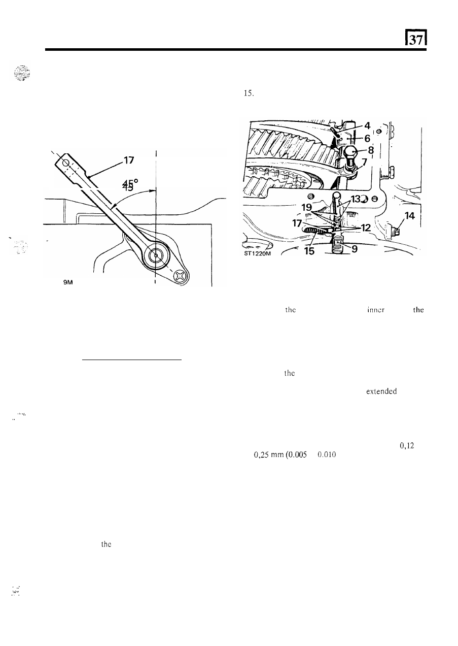
15.  Select  ‘High’  transfer  range,  that  is,  the  larger 

intermediate gear engaged. 

16.  Slacken the selector finger bolt. 
17.  Rotate  the  cross-shaft  until  the  gear  lever  is 

inclined 45 degrees to the vertical position. 

ST 

21 

18.  Tighten t h e  selector finger pinch bolt. 
19. 

Fit  the  top  cover  using  a  new  joint  washer  and 
evenly tighten  the retaining bolts. 

.... 

. . 

.. 

REMOVE  AND  OVERHAUL  TRANSFER  BOX 
SELECTORS AND SHAFT 

1. 

Remove the speedometer drive housing. 

2.  Remove t h e  transfer gearbox top cover. 
3.  Select ‘Low’ range transfer gear. 

4.  Drive  out  the  retaining  pin  from the  front  selector 

fork sufficient to free t h e  fork. 

5 .   Ease the differential 

u n i t  to 

t h e  

rear. 

6.  Push  the  forward  selector  fork  forward  on  t h e  

shaft. 

7. 

Pull  to  the  rear  on  the  rear  selector  fork  to  move 
the  selector  shaft  out  of  engagement 

with 

t h e  

detent balls 

in 

casing rear face. 

8.  Remove the pinch bolt o n  the rear fork. 
9. 

Partially withdraw the selector shaft and  lift out the 
selector forks. 

1 . .  

10.  Remove the retaining pin  from the front fork. 

.  . 

11. 

Withdraw 

t h e  

selector  shaft,  closing  the  shaft 

housing  by  hand 

to  prevent  the  detent  balls  from 

dropping into the casing. 

12.  Withdraw the two detent balls. 
13.  Lift out the spacing rod and spring. 
14.  Remove the blanking plug. 

Withdraw the detent spring from the cross drilling. 

Assemble 

shaft 

and 

selectors 

16.  Position 

detent spring 

in 

t h e  

bore 

in 

17.  Locate the detent ball 

on the spring. 

18. 

Enter 

t h e  

selector  shaft,  push  the 

ball 

against  the 

spring and push 

in 

the shaft. 

19.  Fit  the  detent  ball,  spring and  spacing  rod  to  the 

vertical  drilling. 

20.  Position 

rear selector fork, plain  face to rear, 

in 

the gearbox. 

21.  Position 

t h e  

front  selector  fork, 

boss  to 

the rear, in the gearbox. 

22.  Align  the  retaining  pin  holes  and  engage  the 

selector shaft in t h e  selector forks. 

23. 

Fit the retaining pin, front fork to shaft. 

24. 

Set transfer gears 

in ‘Neutral’ position. 

25.  Adjust  the  rear  fork  position  until  there  is 

to 

to 

in) clearance between  the 

front  face 

of 

the 

rear fork  and  the rear  face of  the 

input gear inner member. 

cross drilling. 

26.  Tighten the rear fork pinch bolt. 

45 

27.  Fit the 

plug 

to 

the cross drilling. 

the  transfer  box  top  cover  using  a  new  joint 

washer and evenly tighten  the bolts to the correct 
torque. 

29.  Fit the speedometer drive housing. 

LT 

95 FOUR 

SPEED GEARBOX 

RER 

E  ND  OVER€ 

SHAFT AND HOUSING 

FRONT 

OUTPUT 

Remove output shaft assembly 

1.  Remove the differential lock actuator assembly. 

2 .   Remove the six  retaining  bolts, spring washers and 

3 .   Withdraw the output shaft and housing complete. 
4.  Lift 

o u t  

the lock-up dog clutch. 

gasket. 

Overhaul assembly 

5. 

Hold  the  output  shaft 

in  a  vice 

or 

use  a  flange 

restraining  tool  and  remove  t h e   flange  retaining 
n u t  

and washer. 

6. 

Withdraw  the  coupling  flange  complete  with 

mudshield. 

7.  If required, press off the mudshield. 
8.  Press out the shaft toward the rear. 
9.  Withdraw the 

seal. 

10.  Remove the circlip. 

Withdraw the output shaft bearing. 

12. 

Wash and 

all parts, examine for wear and 

renew as necessary. 

ST 

Assemble output shaft assembly 

to 

housing 

13. 

Fit 

t h e  

output  shaft  bearing  and  secure  with  the 

14. 

Fit the 

oil 

seal, lip side towards 

the 

bearing. 

15.  Press in the output shaft from t h e  rear. 

16.  Fit 

t h e  

coupling  flange  complete  with  mudshield 

and flange bolts. Secure with  the locking nut  to the 
correct torque. 

ci 

p. 

46 

LT 95 FOUR SPEED GEARBOX 

REMOVE  AND  OVERHAUL 

BELL  HOUSING  AND 

REMOVE  AND  OVERHAUL  GEAR  CHANGE 

CLUTCH RELEASE 

SELECTORS 

I .  

Withdraw  t h e   locating  staple  from  the  clutch 

2.  Lift out the release sleeve and bearing assembly. 
3.  Remove  the  bell  housing  fixings and  make  a  note 

4.  Withdraw  t h e   bell  housing  complete  with  clutch 

5. 

If  required,  remove  the  push  rod  clip  and  the 

release 

and release lever. 

of the position of  each bolt and 

nut. 

release lever. 

spring clip and withdraw the clutch release lever. 

1.  Remove the bell  housing. 

2.  Select neutral, remove the reverse light switch  and 

remove 

the gearbox top cover and joint washcr. 

3.  Lift o u t  t h e  dctent springs. 
4.  Withdraw the detcnt balls, using  small magnet  or 

5 .   Slacken the pinch  bolt  securing the reverse selector 

6.  Drive out the four retaining pins until the shafts are 

an air blast. 

finger. 

free in the selectors. 

Assemble clutch release 

and bell housing 

7.  Tap out 

selector shafts. 

6. 

If removed, 

fit 

the release lever spring clip. 

7.  Apply  a  thin  film  of  Unipart  Universal  or  other 

suitable  jointing  compound  around  the  three 
selector shaft holes 

in 

the bell  housing rear face. 

8.  Fit the bell housing, locating on the dowels. 
9.  Apply  thin film of 

grease 

onto the f r o n t  cover extension sleeve. 
Fit 

rclcase sleeve and bearing assembly. 

11. 

Fit 

the  locating  staple  to  the  clutch 

sleeve 

and lever. 

8.  Withdraw the selector jaws and forks. 

9.  Withdraw  the  two  interlock  plungers  from  the 

cross-drilling. 

10. 

Rcmove 

t h e  

lock-wired pivot bolt. 

11.  Lift out the reverse cross-over lever. 

Overhaul 

Examine all parts and renew i f  worn. Renew 

detent 

springs.  Ensure  that 

t h e  

retaining  pins  are  an 

interference 

fit, 

if 

not, renew. 

ST 

47 

LT 

95 

FOUR SPEED GEARBOX 

Assemble gear change selectors 

12.  Withdraw the retaining pins from the selector jaws. 
13.  Engage the cross-over lever and  locate fully 

in 

the 

groove 

in  the  reverse  idler  with  the  peg  in  the  top 

of the cross-over lever fully in the selector finger. 

14.  Start the  pivot  bolt  in  the  lever  threads.  Should it 

not  start  properly  move  the  lever  away  from  the 
selector  finger  but  not out of  engagement with  the 
idler. 

15.  Locate  the 

gear  selector  fork 

in 

the 

groove  in  the  outer  member, with  the  boss  on  the 
fork to the 

Position  the boss to the 

R.H. side 

of  the box. 

16. 

Locate  the 

gear  selector  fork  in  the 

groove 

in  the outer member. Position the fork with 

the retaining pin entry hole at the top 

R.H. side. 

17. 

Fit  the 

gear  selector  shaft  and 

interlock  pin  assembly  and  secure  to  the  selector 

18.  Fit  the  two interlock  pins  to engage in  the grooves 

each side 

of  the 

gear selector shaft. 

19.  Position  the  reverse  stop  hinge  plate  and  selector 

j a w  

in  t h e   gearbox,  adjacent  to  t h e  

gear selector jaw. 

20.  Fit  the  reverse  gear selector shaft  and  engage  the 

selector jaw and 

spring. 

21.  Push  the shaft  home and engage the reverse cross- 

over lever  selector finger. 

Do not secure the pinch 

bolt at this stage. 

22. 

Secure 

gear  selector  jaw 

to 

the  shaft 

with a retaining pin. 

fork with a retaining pin. 

24  23 

15 

25 

1227M 

gearbox. 

24. 

Fit 

the 

gear selector shaft; engage  the 

selector jaw and selector fork 

as the shaft is pushed 

home. 

25. 

Fit the retaining pins, fitting the rear pin first. 

26. 

Move  the  reverse  shaft  forward until  the  selector 

jaw abuts the casing. 

27.  Holding  the  reverse  shaft  as  described 

in  the 

previous  item,  move  the  reverse  selector  finger 

forward on  the shaft until  it  abuts the casing,  then 

it 

rearward until it is just clear of  the casing. 

28. 

Place  a 

(0.010 in)  feeler  gauge  between 

the  upper  edges  of  the  reverse  and 
selector jaws. 

NOTE: The edges of the selector jaws taper slightly, 
therefore, 

it 

is  important  that  the  feeler  gauge  is 

positioned between the upper edges. 

29.  Hold  the  reverse  and 

selector  jaws 

together to  retain  the  feeler gauge, then  rotate the 
reverse selector finger until it abuts the 
selector shaft and tighten the pinch bolt. 

30.  Wire lock the cross-over lever pivot bolt. 
31.  When  fitting  the  hinge  spring  to  the  reverse  stop 

hinge,  first  engage 

t h e  

large  hook  around  the 

selector shaft, as illustrated,  before fitting the small 
hook 

to 

the reverse stop hinge pin. 

48 


Content   ..  77  78  79  80   ..