Defender 90 / 110 / 130. Manual - part 77
TRANSFER
GEARBOX
.-
.
I
:
.
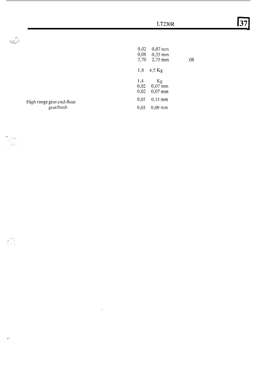
DATA
.......
..
.......
....
Input shaft bearing pre-load
..................................
Intermediate gear end-float ..................................
Centre differential rolling resistance
-
(minus
intermediate gear cluster and output shaft flange)
......
Input gear rolling resistancc
-
(minus
intermediate gear cluster) .....................................
Differential pinions backlash
.................................
Output shaft bearing pre-load
...............................
Low range gear end-float
Intermediate gear thrust washer thickness ................
.....................................
High range
running clearance diameter ......
to
(0.001 to 0.003 inch)
to
(0.003 to 0.014 inch)
to
(1.06 to 1
in)
to
(4
to
10 Ib) pull
to 3,6
(3
to
8
Ib)
pull
to
(0.001 t o 0.003 inch)
to
(0.001 to 0.003 inch)
to
(0.002 to 0.006 inch)
to
(0.0012 to 0.0035 inch)
,
37