Defender 90 / 110 / 130. Manual - part 40
LITRE DIESEL ENGINE
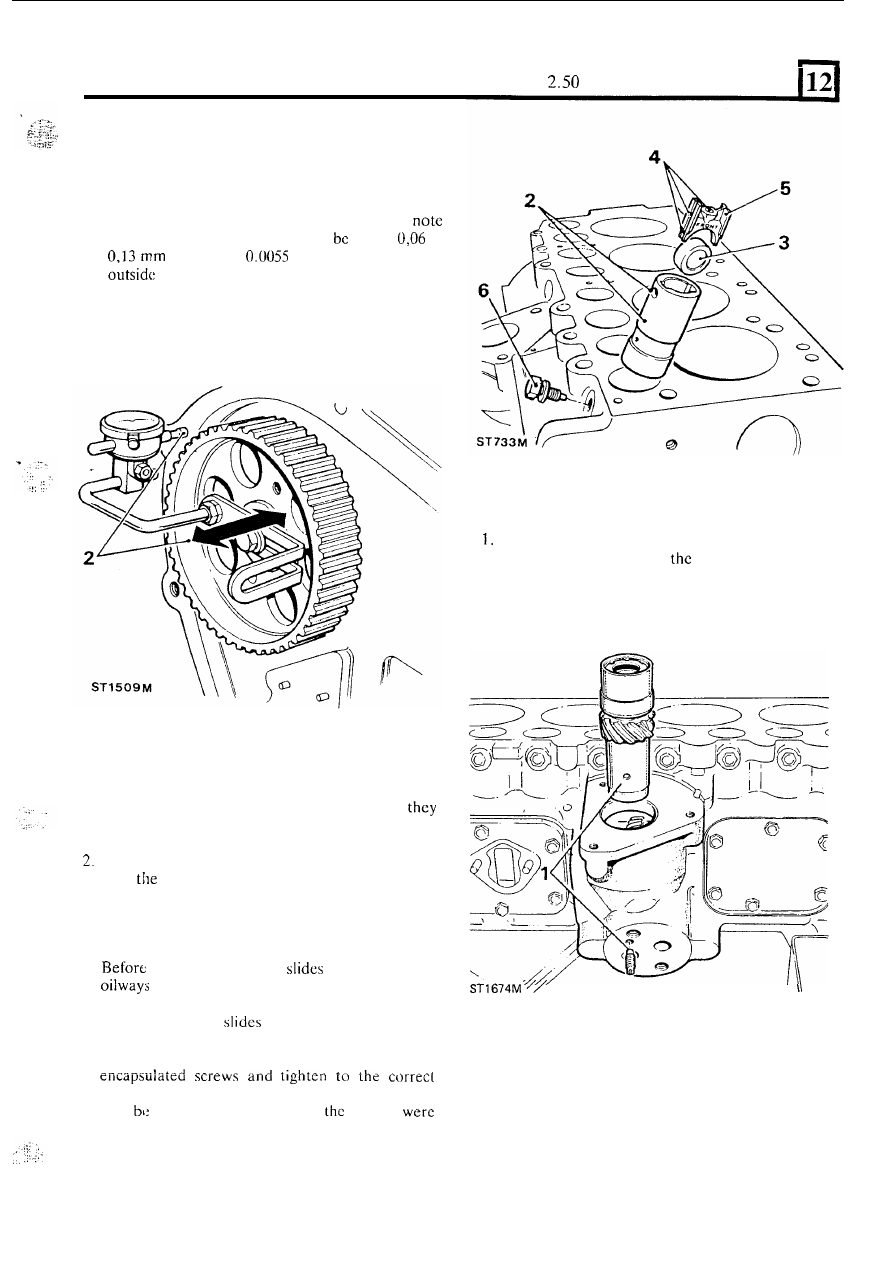
2.
To
check t h e camshaft end-float, fit t h e woodruff
key and temporarily
fit
the cam-shaft pulley and
mount
a dial test indicator, as illustrated, so that
the stylus rests
i n
a loaded condition upon
t h e
machined face of the cylinder block.
Zero the dial
and move t h e camshaft back and forward and
the reading. The end-float should
within
to
(0.0025 to
in). I f the end-float is
these limits,
fit
different thrust plates until
the correct tolerance is achieved.
3 . Remove the test indicator and pulley, and secure
the thrust plate with
t h e
two bolts.
FIT TAPPETS,
GUIDES AND ROLLERS
1. If the same parts are being refitted ensure that
are returned to
their
original positions. Ensure that
t h e
tappet slides move freely i n the guides.
Insert the tappet guides into the cylinder block and
align
locating screw holes.
3.
Fit the tappet rollcrs ensuring that they are fitted
in
accordance with the marks made during removal.
N e w
rollers,
however, may be fitted either way
round.
4.
fitting the tappet
make sure the
are clear
to
the tappet bearing surface, the
cross drilling and the oil feed
to
the push rod.
5. Insert the tappet
with
the word 'FRONT'
towards the front of the engine.
6 . Secure the tappet guides
with
NEW Micro
torque figure. Micro encapsulated screws should
also
used on engines where
screws
originally wired for security.
FIT THE SKEW GEAR
Lubricate and insert the skew gear and coupling
assembly into mesh with
camshaft gear. Align
t h e
location hole
in the bush and
fit
a
new location
screw into
ihc
cylinder block.
I
FIT THE FLYWHEEL
1
Examine the
flywheel
and crankshaft mating faces
and remove any burrs or imperfections that could
prevent
t h e
flywheel locating correctly. Check that
the
dowel is
in position.
continued
79