Defender 90 / 110 / 130. Manual - part 41


  Index      Land Rover     Defender 90 / 110 / 130 - service repair manual


Search            


Content   ..  39  40  41  42   ..


Defender 90 / 110 / 130. Manual - part 41


2.50 LITRE 

DIESEL ENGINE 

-. 

'.- 

13. 

Remove the plug from the side of the D.P.S. pump 

.. 

and  insert  gauge 

tool 

1458  and  if  necessary 

rotate  the pump  body  until 

the  gauge can  be  fully 

inserted  and  screwed  home  indicating  that  the 
inner disc is centrally positioned with the hole. 

14. 

Evenly 

tighten  the three nuts securing the pump to 

the cover and the single n u t  and bolt to the support 
bracke 

t . 

Align  timing  pointer  on  rear  of  cover,  with  the 

scribed 

line on the pump flange and tighten t h e  two 

screws. 

If 

a new pump is being fitted and there is n o  

scribed  line,  scribe  a  line 

in  the  centre  of  the 

machined  area  on 

pump  flange.  Align  the 

timing  pointer  and  tighten  the  screws.  On  later 

engines  the  timing  pointer  has  been  deleted  and 
instruction 

can be ignored. 

16.  Tightcn 

D.P.S. pump timing pulley 

n u t  

and 

camshaft  pullcy  retaining  bolt  to  the  correct 
torque. 

17. 

Remove  the  timing  pointer  from  t h e  

housing,  close  the  cover  and  secure  with  the  two 

nuts. 

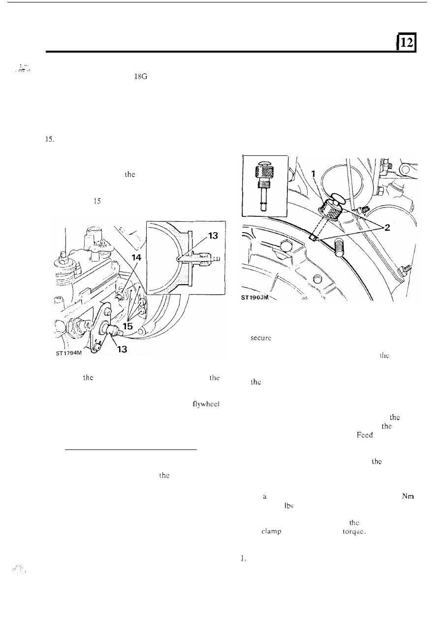
1.  Remove the plug from the 

flywheel housing and fit 

t h e  

body of special 

tool 

LST 107 without the pin. 

2.  Turn  the  crankshaft 

in 

a  clockwise  direction  until 

t h e  

E.P. slot in the flywheel is  in-line with the hole 

in  the  flywheel  housing. 

If  the  crankshaft  is 

inadvertently turned  beyond  the  E . P .  slot,  do  not 
turn the crankshaft back but continue on round 

in 

clockwise  direction  until  the pin  of  the special  tool 
can be fully located i n  the flywheel slot. 

3.  Fit  the  timing  belt  tensioner  assembly  and  loosely 

with  the two nuts. 

4. 

Turn 

t h e  

D.P.S.  pump  pulley  clockwise 

until 

the 

dot on  the pulley  lines-up exactly  with 

cast-on 

arrow inside the front cover. 

5.  Similarly,  t u r n   the  camshaft  pulley  clockwise  until 

dot lines-up with  the cast-on arrow in  the front 

covcr. 

6.  Fit a new timing belt over the crankshaft pulley and 

whilst  keeping t h e  belt  under tension,  by  hand, run 
the belt  over the camshaft  pullcy.  Should 

belt 

not  quite  mate  with  the  grooves,  turn 

pullcy 

clockwise the necessary amount. 

the belt over 

t h e  

D.P.S. pump  pulley  and  if  necessary 

turn 

the 

pulley  clockwise  to locate 

in 

the  grooves.  Keeping 

firm  grip 

on  t h e   belt,  pass 

i t  

over 

tensioner 

jockey pulley. 

7.  Withdraw  the  special  tool  timing 

pin 

from  the 

Time 

D.P.S.  PUMP  AND  VALVES 

Later  Engines 

with slot in flywheel for determining 

E.P. 

The  D.P.S.  pump  and  valves  are  timed  using  the 
exhaust  valve  peak 

of number  one  cylinder.  This  is 

determined 

on 

later engines by  the relationship of 

a slot 

in  the  flywheel  periphery  and 

a  plugged  hole  in  the 

flywheel  housing  through  which 

flywheel  timing  pin, 

special tool number 

LST 107, is inserted. 

-

-  

flywheel slot. 

8.  Set 

dial  type  torque  wrench  to 

20.0 to 

23.5 

(21  to  17 

f t )  

and  whilst  holding 

it 

vertically, 

insert  the  drive  peg  into  the  square  hole  in  the 
tensioner  base  plate.  Tension 

belt  and  tighten 

iiie 

n u t s  

to 

the correct 

9. 

Rotate 

t h e  

crankshaft 

TWO complete revolutions. 

10.  Slacken the tensioner clamp nuts. 

Tension  the belt  again 

as described  in  instruction 

and tighten 

the 

clamp nuts to the correct torque. 

83 

CAUTION:  The  double  tensioning  procedure  is 
imperative  otherwise  the  belt  could  fail  resulting  in 

serious  engine  damage. 

Also,  if  a  new  belt  is  not 

attainable  and  it 

is  necessary  to  refit  the  old  belt  it 

should be 

only torqued to 19-24 

(14-18 

ft). 

2.50 

LITRE DIESEL ENGINE 

12.  Rotate  the  crankshaft  until  the  pin  of  the  special 

timing  tool  can,  once  again,  bc  inserted  into  the 
flywheel 

E.P. slot. 

13.  Check  that 

t h e  

dots  on  the  camshaft  and  D.P.S. 

pump pulleys 

exactly with their respective 

cast-on  arrows  on 

rcar covcr. Should  there  be 

any misalignment  the foregoing procedure must  be 

14.  Remove the plug from the side of  the 

D.P.S. 

pump 

and  insert  special  tool 

1458 and  if  necessary 

rotate  the  pump  body  until  the  tool  can  be  fully 
inserted  and 

home  indicating  that  the 

inner disc is centrally positioned with the hole. 

15.  Evenly  tighten  the  three  nuts  securing  the  pump 

flange to the rear cover  and the single nut  and bolt 
to the rear support bracket. 

16.  Align  the  timing  pointer 

on 

rcar  of 

cover 

with  the  scribed  line  on  the  pump  flange  and 
tighten  the  two  screws.  If  a  new  pump  is  being 
fitted and there is no scribed line, scribe one 

in 

the 

centre  of  the  machined  area 

on 

flange.  Align 

the  pointer  and  tighten  the  screws.  Remove  the 
special  tool 

18G 

1458  and  refit  plug.  The  timing 

pointer has been deleted on later engines. 

17.  Remove the special tool LST 107 and refit the plug 

to the flywheel housing. 

18.  Tighten  the 

D.P.S.  pump  pulley  nut  and  the 

camshaft  pulley  retaining  bolt  to  the  correct 
torque. 

Care 

of belts 

1.  Drive  belts must  be stored o n  cdge 

on  a clean  flat 

surfacc  and  in  such  a  manner  that  bends  are  not 
less than 2  in 

(50 

radius. 

2.  When  a  belt  is  handled, 

it 

must  not  be  bent  at an 

acute  angle  or an  arc of  less  than  1 in 

(25 

in 

diameter,  as  damage 

be 

caused 

the  glass 

reinforcement  and  premature  failure  then 

result. 

3. 

During  use,  a  belt  develops  a  wear 
thereforc,  if 

it 

is  to  be  re-used,  before  removal, 

mark the direction 

of  rotation, using soft chalk or a 

similar  marker, and  refit the belt 

so that 

it 

runs 

the original 

4.  Belts  must  be  dry  and 

FREE 

FROM  ANY  OIL 

O R  

OTHER 

FLUID CONTAMINATION. 

5 .   Do not turn  the crankshaft by  applying leverage to 

the 

camshaft pulley or its retaining bolt. 

6. 

To  remove  a  belt  always  use  clean  hands,  or  a 
recommended tool 

NEVER use a lever. 

84 

2.50 

LITRE DIESEL ENGINE 

FIT 

FRONT 

COVER 

WATER 

PUMP 

AND 

CRANKSHAFT PULLEY 

1.  Place a new joint  washer in position  and insert  the 

centre 

65 

long bolt into the cover with the fibre 

washer on 

inside. 

2.  Fit  the  cover over  the  dowels  and secure  with  the 

remaining  various  length  bolts 

in  accordance  with 

the  chart.  See 

“Fit 

timing  rear  cover,  seals  and 

pulleys”.  Tighten evenly 

to the correct torque. 

3. 

Fit the vent cover gauze and gasket and secure with 
the four bolts. 

4. 

Fit  a  new  crankshaft  seal.  Using  special  seal 
replacer 

tool 

1456  and  with  the  lip  side 

leading, drive in the seal up to the shoulder. 

Fit 

water pump and 

crankshaft pulley 

5.  Place  a  new  joint  washer  in  position  and  offer  up 

the  water  pump.  Fit  the  different  length  bolts  in 
accordance with  the diagram  and evenly  tighten  to 

correct torque. 

6. 

Fit  the  crankshaft  pulley  and  secure  with  the 
special  washer  and  bolt.  Tighten  to  the  correct 
torque figure. 

FIT 

OIL PUMP AND SUMP 

Fit the longer splined end 

of 

the drive shaft into the 

oil 

pump. 

Fit  the 

oil  pump and  drive shaft  to  t h e  crankcase, 

whilst  revolving  the  shaft  as  necessary  to  engage 
the splines 

of  the skew gear. 

3.  Using  new  lock  washers,  secure  the  pump  to the 

crankcase tightening the bolts to the correct torque 
and bend over the lock tabs. 

4.  If  necessary  adjust  the  position 

of  the  strainer  so 

that it is parallel to the sump baffle plate. 

5 .  

Clean the sump and crankcase mating faces and fit 

a  new  joint  washer.  Later  engines  without  a joint 
washer,  apply  a  bead 

of  RTV  HYLOSILL  102 

black 

wide to the sump or cylinder block. 

Secure  the  sump  with  the  twenty-one  bolts  and 
spring washers  and  one nut.  Evenly  tighten  to  the 
correct torque. 

FIT  CYLINDER  HEAD  AND  ROCKER  SHAFT 
ASSEMBLY 

1.  Clean t h e  cylinder head  and cylinder block  mating 

faces.  Position  a  new  cylinder  head  gasket 

on 

the 

cylinder block with the word  ‘Diesel’ uppermost. 

2.  Lower  the  cylinder  head  onto  the  cylinder  block 

using  two  long  bolts  to  facilitate  accurate 
positioning 

of  the head. 

3. 

Fit  the  cylinder  head  retaining  bolts  except  those 
also  used  to  secure  the  rocker  shaft  and  leave 

finger-tight. 

4.  Insert  the  push  rods  ensuring  that  the  ball 

locates properly in the spherical seat in the tappet. 

5.  Whilst  holding the rocker shaft assembly together, 

lower 

it 

into position  making  sure that  the  hollow 

dowels  locate  properly  in  the  cylinder  head.  Also 
ensure  that  the  rocker  adjusting  screw  ball  end 
locate in the push rods. 

6.  Fit the  rocker  shaft large  retaining bolts  and  leave 

finger-tight. 

2.50 

LITRE DIESEL ENGINE 

7.  Tighten 

cylinder  head  retaining  bolts,  evenly, 

to  the  correct  torque  figure 

in 

sequence 

illustrated below. 

8. 

Fit  and  tighten  the rocker  shaft, small  bolts  to the 

specified torque. 

5 .  

Continue  to  check  and  adjust 

remaining 

tappets in  the following sequence: 

Set N o .  

3 tappet with No. 6 valve fully open. 

Set 

No. 5 

tappct 

with 

No. 4 valve fully open. 

Set 

No. 

2 tappct 

with 

N o .  7 valve fully open. 

Set 

No. 

8 tappet with No. 1 valve  fully 

Set No. 

6 tappet 

with 

No. 3 valve fully open. 

Set 

No. 4 tappet with  No. 5 valve fully open. 

Set 

No. 

7 tappet with N o .  2 valve fully open. 

Fit the rocker cover 

6.  Using a new gasket, fit the rocker cover and secure 

with  the dome nuts and washers. Tighten evenly  to 
the correct torque. 

Do not overtightcn. 

ADJUST TAPPET CLEARANCES 

ST 880M 

FIT 

THE CLUTCH 

1.  Clean  the  flywheel  face and  place  the centrc plate 

with  the  side  marked  ‘Flywheel  side’ towards  the 
flywheel. 

1. 

the  crankshaft  is  rotated  with 

valve 

2. 

Fit  the  clutch  assembly  locating 

i t  

over  the  three 

clearances, 

it 

is  possible  that  the  push  rods  may 

dowels and loosely securc 

with 

six bolts. 

3. 

Centralise  the  centre  plate  using  special  tool 

fracture  the  tappct  slide.  To  prevent  damage, 

or 

primary  shaft and  tighten 

six 

eliminate  all  clearance  from  any  loose  rockers 

bolts evenly to the correct 

figure. Smear 

before  turning  the  crankshaft  to  adjust 

splines  of 

centrc  plate  with  Molybdenum 

clearances. 

grease, such as Rocol 

1000. 

Turn  the  engine  over  until  number  eight  valve 
(counting from front 

of  engine) is fully open. 

3. 

Using a 

(0.010 

in) feeler gauge check  the 

clearance between  the  valve  tip and  rocker  pad  of 
number one valve. 

4. 

Adjust the clearance by slackening the lock n u t  and 
turning 

t h e  

tappet  adjusting  screw  clockwise  to 

reduce  clearance  and  anti-clockwise  to  increase 

clearance.  Rechcck  the  clearance  after  tightening 
the lock nut. 

86 


Content   ..  39  40  41  42   ..