Defender 90 / 110 / 130. Manual - part 39


  Index      Land Rover     Defender 90 / 110 / 130 - service repair manual


Search            


Content   ..  37  38  39  40   ..


Defender 90 / 110 / 130. Manual - part 39


LITRE DIESEL ENGINE 

.. 

... 

... 

3 .   Locate  the  crankshaft 

in 

position 

on  the  upper 

bearing  halves  in  the  crankcase  and  wipe  any  oil 
from  the  ,journals since  ‘Plastigauge’ is 

i n  

oil.  Place  a  piece  of  ‘Plastigauge’ across the  lower 
half  of  each  crankshaft  journal  or  lower  bearing 
cap 

Fit 

the  cap  and  tighten  to  the  correct 

torque.  Remove the cap and  bearing and  using the 

scale  supplied  with  t h e   ‘Plastigauge’  measure  the 
flattened  ‘Plastigauge’  at 

i t s  

widest  point.  The 

graduation  that 

most 

closely  corresponds 

with 

width  of  the  ‘Plastigauge’  indicates  the  bearing 
clearance. 

correct  clearance  with  new  or  overhauled 

components  is  included 

in 

“General  specification 

data”  section.  If  new  bearings  are being  fitted  use 
selective  assembly  to obtain  the  correct  clearance. 
Wipe  off, not scrape  the  ‘Plastigauge’ with  an  oily 
rag 

from the journals 

or bearings. 

Adjust crankshaft end-float 

5. 

Place  the  crankshaft 

in 

position  in  the  crankcase 

and  mount  a dial  test  indicator  to read-off  the end 

of  the  crankshaft.  A  feeler  gauge 

used 

instead of an indicator. 
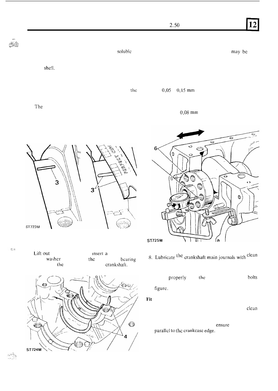
6. 

Determine the end-float  by  moving  the  crankshaft 

away  from 

t h e  

indicator  and 

zero  the  dial.  Move 

the  crankshaft 

i n   the  opposite  direction  and  note 

the  indicator  reading.  Alternatively  measure  the 

clearance 

with 

a feeler gauge. The end-float should 

be 

to 

(0.002 to 0.006 in). 

7. 

If  adjustment  is  required  substitute  with  oversize 

thrust  washers.  Variation  of  thrust  washer 
thickness  at  each  side 

of  crankshaft journal  must 

not  exceed 

(0.003 in) 

to 

ensure 

t h a t  

the 

crankshaft remains centralised. 

4. 

the  crankshaft and 

standard  size 

engine oil  and 

fit 

the appropriate bearing caps and 

lower shells to the crankcase 

with 

the exception  of 

thrust 

both sides of 

centre main 

saddle with 

grooves towards the 

number  five  main  bearing.  Ensure  that  the  caps 
locate 

o v e r  

dowels.  Using  new 

and  washers  evenly  tighten  to  the  correct  torque 

rear main 

hearing 

cap 

9.  Ensure  that  number  five main  bearing cap is 

and free from old cork seal material. 
Attach  the  cork  seal  guides  number 

270304 

to 

the 

crankcase, as  illustrated,  and 

that  they  are 

75 

2.50 

LITRE DIESEL 

ENGINE 

ST 

10. 

prevent  any  cork  seal  material  becoming 

trapped  between  the  bearing  cap  and  crankcase, 

chamfer  the  inner  edge  of  the  corks 

to 

to 

in) wide 

as illustrated. 

Immcrsc the cork seals in  engine oil and 

fit 

them  to 

bearing cap. 

11. 

Fit the bearing cap and lower shell to the crankcase 
and secure with  new  bolts  and washers  and  tighten 
to the appropriate torque. 

12. 

To  allow  for  shrinkage  after  fitting  leave  the  cork 
seals standing proud  of  the crankcase sump face. If 
possible  delay  the  fitting  of  the  sump  for 
approximately  twelve  hours  and  leave 

t h e  

seal 

protruding 

in)  and  then  place  a 

in)  washer  over 

seal  and  cui 

the  surplus.  If  it  is  necessary  to  fit  the  sump 
immediately,  trim  the  seals  off  leaving 

in)  proud,  that  is, 

t h e  

thickness  of  t h e   above 

washer. 
Apply  Hylomar 

to  the  protruding  end  of 

the seals. 

Fit rear main oil seal 

13.  Check  that  the  crankshaft  oil  seal  journal  is 

undamaged  and clean. Make sure the seal  housing 
is clean and  dry and free from  burrs. 

Do not  touch 

the seal  lip  and  ensure that  the outside diameter is 

clean  and  dry.  The 

Seal  Part  No. 

5369  which  should  be  used  is  supplied  with  a 
former to maintain  the correct shape and  must  not 
be removed until the scal is to be fitted. 

14. 

Using special seal replacer 18G 134-1  and 

the 

lip  side  leading  drive-in  the  seal  as  far  as  the  tool 
allows. 

If the 

tool 

is not available 

fit 

scal 

to the 

bottom 

of  the housing 

to 

ensure squareness. 

ST 

1828M 

Fit flywheel housing 

Early engines 

16.  Examine  the  seal  guide  number 

1344  and 

repair any damage that could destroy the seal lip. 

17.  Lubricate  the  outside  diameter  of  the  seal  guide 

and t h e  seal journal with  concentrated ‘Oildag’ in a 
25% solution with clean engine oil. 

76 

2.50 

LITRE DIESEL 

ENGINE 

18. 

Place  the  seal  guide 

o n  the  crankshaft flange  and, 

using  the  two dowels protruding  from  the  cylinder 
block  rear  face  as  a  guide  to  ensure  initial 
squareness,  fit  the  flywheel  housing  and 
the 

guide.  Secure the flywheel  housing  evenly 

tightening the retaining bolts. 

Fit flywheel housing 

Later engines 

19. 

In place 

of  the 

ring seal a bead 

of 

Hylogrip 

2000 

sealant  must  be  applied 

to 

the  rear  facc  of  the 

flywheel 

housing 

to 

the 

dimensions 

and 

configuration  as illustrated  below.  The illustration 
has been  produced  full  size 

so that a template  may 

be  made to facilitate  the  application of  the sealant. 
The  bead  should  be 

wide  and 

thick. 

20.  Fit the housing following instructions 17 to  19. 

77 

LITRE DIESEL ENGINE 

FIT 

THE CONNECTING-HODS AND PISTONS 

1.  Turn  the  crankshaft to  position  numbers  one and 

four crankpins  at  bottom  dead  centrc  to 

fitting 

connecting-rods. 

2.  When  fitting  the  connecting-rods  and  pistons 

ensure  that  t h e  bolts  d o  not  foul  and  damage  the 
crankpins. As 

a precaution  it  is recommended that 

rubber  or  soft  plastic  sleeves  are  placed  over  the 
threads. 

3 .   The  connecting-rod  bolts  have  essentric  heads 

which  locate  in  a  recess in  the connecting-rod.  It  is 
essential that the head 

of  each new  bolt is properly 

located before tightening. 

4.  Stagger  the compression  rings 

so that  the  gaps  are 

equidistantly  spaced  round  the  piston  but,  so 
arranged,  that  n o  

gap  is  positioned  on  the  thrust 

side  of  the  piston 

opposite 

t h e  

camshaft. Turn 

the oil control ring 

so that the gap is 

in 

line with the 

gudgeon pin. 

5 .   Lubricate  the  cylinder  walls,  piston  rings  and 

crankpins.  Compress 

t h e  

pistons  rings  with  a 

suitable  compressor  tool  and  carefully  lower  the 

connecting-rod  into  the  bore  ensuring  that  the 
piston  is  assembled  in  accordance with  instruction 
27 under “Assemble pistons to connecting-rods”. 
Also 

the 

point  of 

arrow 

valve clearance 

indentation 

in 

the  piston  crown,  must  face  the 

camshaft side of  the engine. 

6.  Using a  soft  mallet,  sharply tap the  piston  into the 

bore  so that 

t h e  

whole  of 

piston  is  just  below 

the surface of 

t h e  

cylinder block. 

78 


Content   ..  37  38  39  40   ..