Defender 90 / 110 / 130. Manual - part 38


  Index      Land Rover     Defender 90 / 110 / 130 - service repair manual


Search            


Content   ..  36  37  38  39   ..


Defender 90 / 110 / 130. Manual - part 38


2.50 

LITRE 

DIESEL ENGINE 

3.  New  Pistons 

Original  pistons  fitted  to  new 

engines  at  t h e   factory  are  specially  graded  to 
facilitate assembly.  The grade  letter on  the  piston 
crown  should  be  ignored  when  ordering  new 
pistons.  Genuine Land  Rover service standard size 
pistons 

supplied  0,025 

(0.001  in) 

to allow 

for 

production  tolerances on new  engines. 

When fitting 

pistons to a standard size cylinder 

block  the 

must  be honed to accommodate the 

pistons 

with 

the  correct  clearances. 

In  addition 

Land Rover pistons are available 

and 

(0.020 and 0.040 in) oversize  for fitting to rebored 

cylinder blocks. 

limits  for  new  standard size  pistons 

in  a 

standard  cylinder  bore  measured 

at  right  angles 

to 

the  gudgeon  pin  are 

in  the  “General  specification 

data” section. 
When  taking  the  following  measurements  the 
cylinder  block  and  pistons  must  be  a t   the  same 
temperature to ensure accuracy. 

Using a suitable micrometer measure the pistons at 

the  bottom 

of 

skirt  at  right  angles  to  the 

gudgeon pin. 

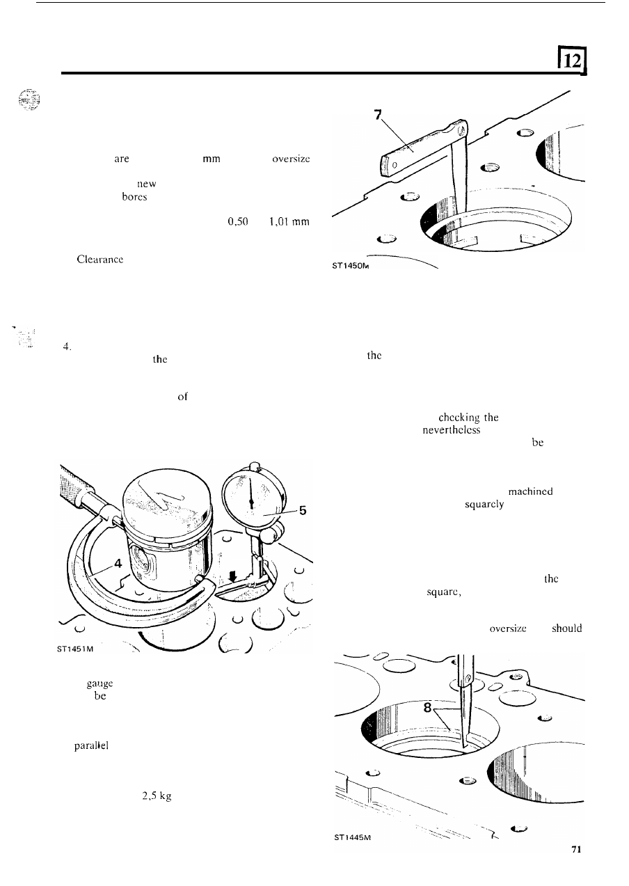
5.  With  an  inside  micrometer 

or 

cylinder  gauge 

measure the diameter 

the bore at approximately 

half-way down and note the reading. 

6.  The  clearance  is  determined  by  subtracting  the 

piston diameter from the bore diameter. 

7 .  If 

equipment  is  not  available  the  clearance 

can 

assessed  by  placing 

long,  suitably  sized, 

feeler  gauge down  t h e   thrust  side 

of  the  bore  and 

inserting the  appropriate piston,  ‘upside down’, 

in 

the  bore  and  position 

it 

with  the  gudgeon  pin 

to  the  crankshaft  axis.  Push  the  piston 

down  the  bore  and  stop  at  the  tightest  point  and 
whilst  holding  the  piston  still, slowly withdraw  the 
feeler 

gauge. 

If 

steady 

resistance 

of 

approximately 

(6 Ibs) is felt, the clearance is 

satisfactory. 

Inspect piston 

rings 

Normally  when  an  engine  is  being  overhauled  the 
piston  rings  are discarded  unless  the pistons  have  been 
removed  for 

a  different  purpose  and  the  engine  has 

only  completed  a  small  mileage.  Before  refitting  the 
piston 

rings  should  be  examined  for  wear  and 

damage. In  addition the rings  must  be checked for side 
clearance in  the pistons and gap 

in 

the 

bores. 

The latter 

two checks must  be made when  fitting new rings to new 
and used pistons. 

8.  Check  gap  When 

ring  gap  in  worn 

bores,  but  are 

within 

the  acceptable 

taper  and  ovality  limits,  the  ring  must 

inserted 

squarely  into the  bottom  of  the  bore  at  the  lowest 
point  of  the piston  travel. 

To ensure squareness of 

the ring push the ring down the bore to the correct 
position  with  a piston. With newly 

bores, 

the ring  may be  inserted 

into any position 

in the bore. 

9.  Using  an  appropriate  feeler  guage check  the  gaps 

of  all  the  rings,  in  turn,  including  the  oil  control 
ring assembly. 
The correct  gaps  are listed  in  the  Data  Section. 

If 

any gap is less than  that  specified, remove 

ring, 

and file the ends 

whilst holding the ring 

in 

filing  jig  o r   vice.  Should  any  gap  be  excessively 

wide  and  not  likely 

to 

close-up  to  within  the 

specified  limits  when  hot,  an 

ring 

be fitted. 

2.50 LITRE DIESEL ENGINE 

Check piston ring side clearance 

10.  It  is  important  that  clearances  are  correct.  Rings 

that  are 

too tight will  bind  when  hot, 

the 

radial 

pressure 

causing 

possible 

loss 

of 

Excessive  clearancc  will  allow  the 

rings 

to 

rock  in  the  grooves  and  the  resulting 

pumping 

action 

could  cause  excessive  oil 

consumption and eventually broken  rings. 

11. 

Fit the oil control ring to t h e  bottom groove. Fit the 

unpolished  compression  ring  with  the  word 

‘TOP’ 

uppermost  to  the  second  groove.  Insert  the 
polished  chrome ring with  an  internal  chamfer  and 
the word 

‘TOP’ uppermost 

to 

the top groove. 

12.  Alter  fitting  each  ring,  roll 

it 

round  the  piston 

groove 

ensure that 

i t  

is free and does not bind. 

13. 

Using  an  appropriate  feeler  gauge  check  the 

clearance 

the  rings  and  piston  grooves. 

in excess 

of  0,012 to 0,152 

(0.004 

t o  

pistons should be renewed. 

0.006  in) are  unacceptable  and  the ring and 

or the 

Connecting-rod  inspection 

16.  Check  the  connecting-rods  and  caps  for distortion 

as  follows;  f i t   the  correct  cap,  less  the  bearing 
shells, 

to  each  connecting-rod  as  denoted  by  the 

number 

near the j o i n t  faces. This number 

also  indicates  the  crankshaft  journal  to  which 

it 

must be fitted. 

17.  Tighten  the  nuts to  the  correct  torque  and  release 

the  nut  on  one  side  only.  Check,  with  a  feeler 

gauge,  that  no  clearance  exists  between  the  joint 
faces. 

If  there  is  a  gap  the  connecting-rod  is 

distorted and should be renewed. 

Compression  rings 

to  0,011 

(0.0025  to 

0.0045 in). 
Oil  control  ring 

0,038  to  0,064 

to 

0.0025  in). 

13 

Inspect gudgeon pins 

14.  Check the gudgeon pin  for wcar, cracks, scores and 

overheat 

15. 

The gudgeon pin  fit in the piston 

be tight push 

f i t  

at  a 

of 

68°F  (20°C).  Chcck  the 

gudgeon  pin  for  ovality  and  taper 

using 

micrometer. 

18.  Use an accurate connccting-rod  alignment gauge 

to 

check 

rods  for  bend  and  twist. 

maximum 

allowable 

for 

both  conditions  must  not  exceed 

0,127 

in). 

19. 

and check the small-end bush 

for wear. If 

necessary 

the bush. The correct clearance of 

the  gudgeon  pin  in 

small-end  bush  is  given  in 

specification data”. 

20.  When 

a  bush  ensure  that  the oil  hole 

in 

the  bush  lines  up  with  the  hole  in 

the connecting- 

rod.  Finish  the  bush 

to 

the  correct  size  and 

clearance. 

bearings  that  are  worn,  pitted, 

scored  and  show  signs  of 

must 

be 

discarded.  If  more  than  one  of  the  bearings  show 

signs they 

must 

all  bc  rcncwed.  When  fitting 

new 

o r  

used  bearings 

to 

crankpins the 

clearances must be checked. 

!f- 

Connecting-rod bearing nip and clearance 

New  bcaring  halves  are  supplied  with  a  protective 
coating and must be degreased before fitting. 
22.  Fit  the  bearing  halves  to  the  connecting-rod  and 

cap  and  secure  the  assembly 

with 

the  correct 

torque. Slacken the nut  on one side only and check 
the clearance between  the joint  faces 

with 

a  feeler 

gauge. 

72 

2.50 

LITRE DIESEL ENGINE 

.... 

The  clearance  should  be  between 

and 

Connecting-rod end-float 

(0.004 and 0.008 in). The bearing nip can 

bearing  shells  which  are  available 

in 

slightly 

varying  thickncsscs.  Do  not  file 

or  machine  the 

caps o r  rods to  vary 

t h e  

bearing  nip.  Make  a  final 

check  to  prove  the  clearance  by  inserting  a  0,063 

26.  Fit  the  connecting-rods complete with  bearings  to 

their  respective  crankpins.  Move  the  connecting- 
rod  to  one  side  and  check  the  clearance,  with  a 

feeler, 

on  the opposite side. The correct clearance 

is between 

and 

(0.007 and 0.012 

in). 

(0.0025 in)  shim  paper  between  the  crankpin  and 

one half 

of  the bearing and tightening to the correct 

torque.  The  connecting-rod  should  resist  rotation 
and move freely with the shim paper removed. 
As  an  alternative,  the  bearing  clearances  can  be 
determined by  using ‘Plastigauge’ which  consists of 

a t h i n  

of  plastic material  a few hundreds of  a 

millimeter  or  thousands  of  an  inch  in  diameter. 
When  the  material  is  flattened  by  being  squeezed 
between  the bearing and crankpin the width of 

plastic is measured by a scale gauge which  indicates 
the clearance. 

Wipe any oil  from the crankpins  and  place 

piece 

of  ‘Plastigauge’ across  the  centre o f  the  bearing  in 
the  connecting-rod  cap.  Assemble  the  rod  to  the 
appropriate  crankpin  and  tighten  to  the  correct 
torque. 

Do 

not  rotate 

connecting-rod  or 

crankshaft during this operation. 

24.  Remove  the  connecting-rod  cap  and  bearing  shell 

and  using  the scale supplied  measure 

flattened 

‘Plastigauge’ 

a t  

its  widest  point.  The  graduation 

that  most  closely  corresponds  to  the  width 

the 

‘Plastigauge’ indicates the bearing 

The  correct  clearance  with  new  or  overhauled 
components  is  0,019  to 

0,063 

(0.0007 

to 

0.0025 i n ) .  

25.  Wipe off the ‘Plastigauge’ with  an  oily rag.  Do not 

scrape off otherwise 

it 

may damage the crankpins. 

23 

Assemble pistons to connecting-rods 

The piston  must  be assembled 

with 

the point of 

the 

on 

piston  crown, 

on  the  same side  as the 

bearing shell location  slots 

in 

the connecting-rod. 

28. 

a circlip 

in  one side of 

gudgeon  pin  boss 

and assemble the piston 

to 

the connecting-rod 

with 

the gudgeon pin. Secure the assembly with a circlip 

on the opposite side of t h e  piston. 

ST 

1448 M 

73 

2.50 

LITRE DIESEL ENGINE 

ASSEMBLE 

ENGINE 

ASSEMBLE JET 

TUBES TO CYLINDER BLOCK 

Oil jet tubes arc fitted to lubricate the pistons and bores 
directly from 

main oil gallery. 

2. 

3. 

The jet 

are 'Handed'  and  can  only  be  fitted 

one  way.  It  is  important  to  note  that  the  jet 
retaining  'bolt'  contains  a  non-return  valve  and 
therefore  on  no account  must  an  ordinary  bolt  be 
used. 
Clean  the  recess 

in  the  cylinder  block  using  an 

air 

line, i f  available, to remove any swarf. 
Assemble 

f i t  

t h e  

jet  tube  assemblies  as 

illustrated ensuring that the pegs 

in 

the holes 

in  the cylinder block,  and that  the  larger diameter 
washer fits under the bolt head. 
Before  tightening  the  retaining  bolts  ensure  that 
the small squirt  pipes d o  not  foul  the crankshaft 

or 

pistons.  Firmly  tap  t h e   jet  tube  assemblies  down 

onto  the  cylinder  block,  thus  ensuring 

t h a t  

the 

locating  dowel  is  fully  home  and  avoiding  any 

sideways  distortion  on  the  retaining  bolt.  Use 
tube slightly larger than  the bolt  head. The old  bolt 
should be discarded and a new bolt  fitted. 

crankshaft  and  pistons  have 

been 

fitted 

slowly  turn 

crankshaft  and  check  that  no 

fouling occurs. 

A .  

Early 

Latest  Assembly. 

FIT CRANKSHAFT 

Main bearing nip and clearance 

New main bearing halves are supplied 

with 

protective 

coating and must be degreased before fitting. 

Fit  the bearing  halves 

in 

t h e  

crankcase saddles and 

caps  and  secure  the  caps  to  the  crankcase  and 
tighten  to 

correct  torque. Slacken  the  bolts 

on 

one side of  the caps only and, with  a feeler gauge, 
check  the  gap  between  the  joint  faces. 
clearance  o r   nip  must  be  within 

to 

(0.004  to 

0.006  i n ) .   The  bearing  nip  can  be 

adjusted  by  selective  assembly  of  the  bearing 
halves  available  in  varying thicknesses. 

Do not  file 

or  machine  the  caps  or  saddles  to  achieve 
correct clearance.  Note that 

rcar main  bearings 

are wider than the 

four. 

2. 

make a 

check  that  the clearance is correct. 

leave  the  bearing 

in 

the  crankcase  saddles 

and  carefully  lower  the  crankshaft  into  position. 
Check 

bearing 

in 

turn by  inserting a 

0,063 

in)  shim  papcr  between 

bearing  cap 

and  crankshaft journal  and  tighten  the  bolts  to the 
correct  torque.  If  the  clearance  is  correct,  thcrc 

should  be  a  slight 

in 

the  resistance 

to 

rotation of the crankshaft. 

As 

an  alternative  'Plastigauge'  may  be 

to 

check the clearance 

in 

the 

manner 

a s  

with  the 

connecting-rod bearings. This material  may also be 

used 

to  determine  the  amount  of 

in 

used 

bearings and 

74 


Content   ..  36  37  38  39   ..