Defender (1993+). Manual - part 119
BODY
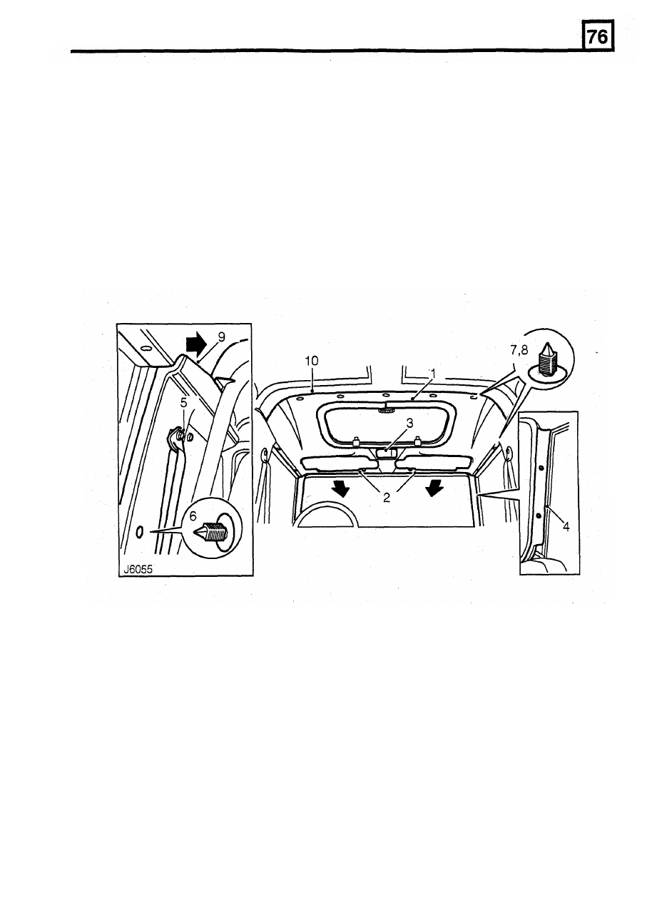
5.
Remove caps and unscrew front seat belt fixing
bolts from 'B/C' posts.
6.
Carefully prise side trim panel cap fastener from
'B/C' posts.
7. Carefully prise
2
trim studs, from both sides,
securing headlining to body at door aperture.
8.
Carefully prise out 5 trim studs securing front
and rear headlinings to roof.
9. From both sides, pull side trim panel inwards
FRONT HEADLINING
Service repair no - 76.64.10
Remove
1.
Remove sun roof headlining finisher.
2. Remove sun visors. See this Section.
3.
Remove interior lamp. See Electrical.
4. Remove 4 retaining screws and detach both
'A'
enough to release rear corners of front
10.
Lower headlining and remove from vehicle.
NOTE: Take care not to bend the headlining on
removal and refitting.
post trims.
15. Fit side trim trim studs at ‘B/C’ posts.
16. Secure seat belts to
'B/C'
posts and tighten bolts
to
32
Nm (24 lbf.ft). Fit caps to bolts.
17.
Fit
' A
post trims.
18. Fit interior lamp. See Electrical,
19. Fit sun visors. See this Section
.
20. Fit sun roof headlining finisher.
Refit
11. With assistance, raise headlining to roof.
12.
Carefully pull side trim panel inwards, on both
sides, and slide headlining behind trim panel.
13. Position front headlining into recess of rear
headlining and secure both to roof mounting
brackets with
5 trim studs.
14. Secure both sides of front headlining to body at
door apertures with trim studs.
11
headlining.