Defender (1993+). Manual - part 82
BRAKING
SYSTEM
20. The shoes in the wheel cylinder piston slots
2.
Disconnect the propeller shaft from the output
and lever the opposite ends into the pivot
flange.
block.
3.
Remove the two screws and withdraw the
21. Operate the snail cams
to
check that the
brake drum. Skim if excessively scored or
shoes respond.
oval.
22. Connect the brake fluid pipe to the wheel
4. Remove the split pin and clevis pin connecting
cylinder.
23. Fit the brake drum and secure with the single
5.
Remove the brake shoes complete with
screw.
pull-off springs. Note position of springs in
24. Adjust each brake shoe independently as
relation to the shoes.
follows:
turn one adjuster until the shoe is
6. Remove the four bolts securing back-plate to
locked
against
the
drum.
Back
off
transfer box and withdraw the back-plate
approximately
two
serrations of the snail cam
complete with oil catcher.
so
that the drum revolves freely.
25. Repeat instruction 24 on the second shoe and
carry out the same procedure for the opposite
brake.
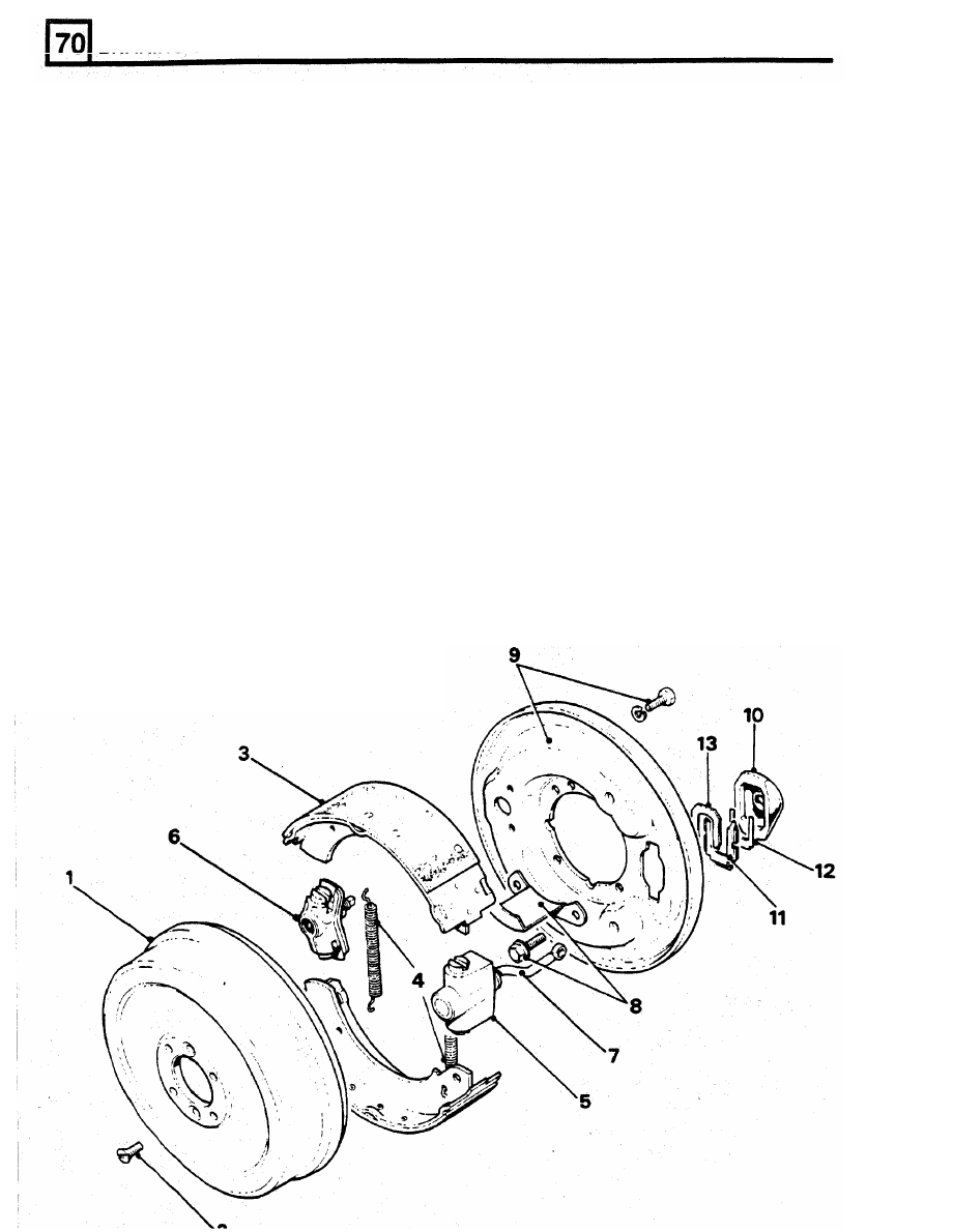
1.
Brake drum.
26. Bleed the brakes.
2. Brake drum retaining screws
27. Fit the road wheels, remove the axle stands
3. Brake shoes.
4. Brake shoes pull-off springs.
6.
Adjuster assembly.
8. Oil catcher.
9. Back plate and retaining bolts.
10. Dust cover.
the drawlink to the actuating lever.
KEY
TO
TRANSMISSION BRAKE
and finally tighten the road wheel nuts to the
correct torque.
5.
Expander assembly.
OVERHAUL TRANSMISSION BRAKE
7. Draw link.
WARNING:
Do
not use an air line to remove dust
from the brake assembly. Asbestos dust from the
brake linings can
be
a serious health risk, if
11. Locking plate.
inhaled.
12. Packing plate.
DISMANTLING
13.
Spring plate.
1.
Disconnect the battery and chock the road
wheels for safety.