Defender (1993+). Manual - part 80
SUSPENSION
FRONT
ROAD
SPRING
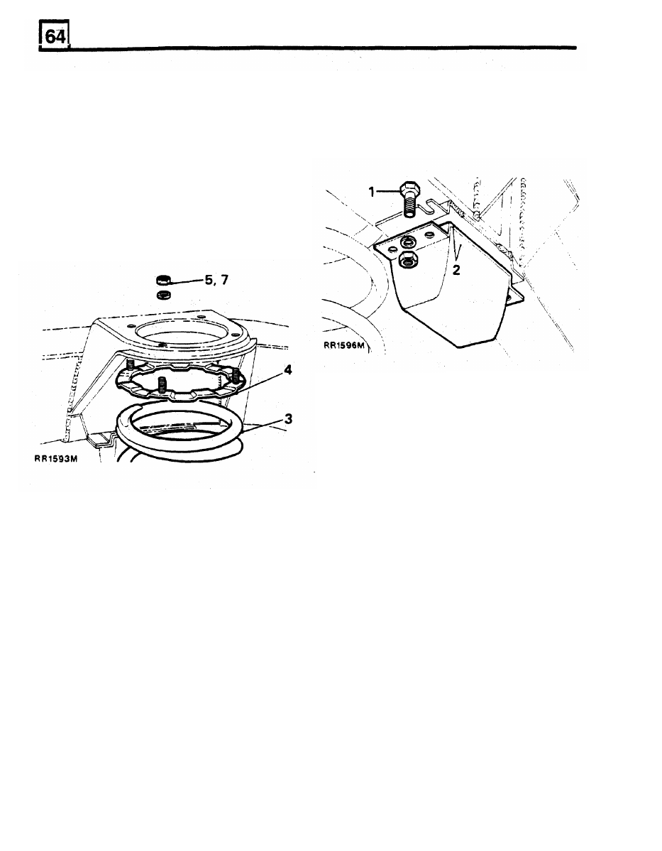
BUMP
STOP
Remove
Remove
1.
Remove front shock absorber.
1.
Remove fixings.
CAUTION: Avoid over stretching brake hoses. If
necessary loosen hose connector locknuts to
allow hoses to follow axle.
2.
Remove bump stop.
2.
Lower axle sufficient to free road spring.
3. Withdraw road spring.
4.
Withdraw shock absorber bracket securing
ring.
Refit
3. Position bolts in slots in chassis brackets.
4.
Fit bump stop, secure with washers and nuts.
Refit
5. Fit shock absorber bracket retaining ring.
6. Reverse
2
and
3.
7.
Remove nut retaining securing ring.
8.
Fit
front shock absorber.
Retain in position with a nut.