Defender (1993+). Manual - part 57
LT230T
TRANSFER GEARBOX
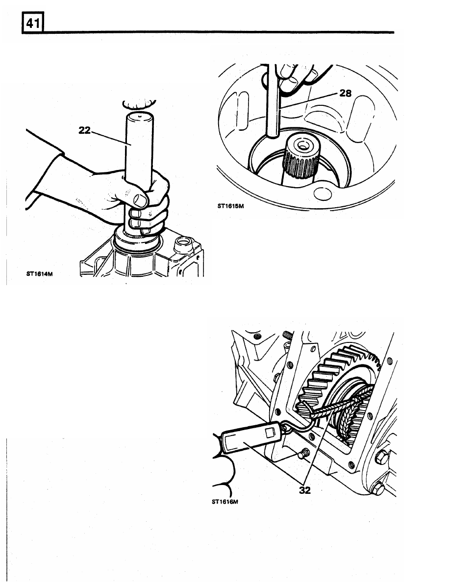
22.
Pre
-
grease and fit a new oil seal (lip side
inwards) using replacer
tool
18G1422,
until
the seal just makes contact with the circlip.
29. Grease and fit new gasket and locate the front
output housing on the transfer box casing.
30. Secure housing with the eight retaining bolts
and washers, the upper middle bolt being
longer than the rest. Do not tighten the bolts
at this stage.
31. Engage high or
low
gear.
32. Check the roiling resistance of the differential
using
a
spring balance and a length
of
string
wound around the exposed splines of the
high/low hub.
23. Carefully charge the lips
of
the seal with clean
grease.
24. Slide collar on to the output shaft, with its
chamfered edge away from the dog teeth.
25. Fit
the output shaft through the bearing and
drift home.
Adjusting front differential bearing pre - load
26. Measure original differential front bearing track
shim.
27. Refit original shim into input housing.
28. Drift differential front bearing track into the
housing.