Defender (1993+). Manual - part 18
 

  Index      Land Rover     Defender - service manual 1993 year


Search            


Content   ..  16  17  18  19   ..


Defender (1993+). Manual - part 18


ENGINE 

ENGINE REMOVAL 

NOTE:  Release  bolts  securing  compressor 
mounting  bracket  to  engine  and  remove  bracket 

Remove 

to  enable  temporary  lifting  eye  ETC 

5964 

to  be 

fitted. 

Secure  lifting  eye  to  mounting  bracket 

1. 

Park  vehicle  on  level  ground  and  apply  park 

fixing  points  with  suitable  bolts  of  equivalent 

brake. 

size,  pitch and  thread.  Leave lifting eye  attached 

2. 

Depressurize fuel  system,  see  Depressurise 

until engine is reinstalled in vehicle. 

fuel system. 

3. 

Remove bonnet, see CHASSIS AND  BODY. 

15. 

Place drain tray underneath vehicle. 

4.  Disconnect battery. 

16.  Disconnect  hose  from  reservoir 

to 

power 

5. 

Remove radiator/oil coolers. 

steering  pump.  Secure  hose  end  above  level 

6. 

Place  an  absorbent  cloth  around  fuel  feed 

of  fluid  reservoir 

to 

avoid  unnecessary 

loss of 

hose at fuel  rail and release compression nut. 

fluid. 

Remove feed hose from rail, seal end of  pipes 

17. 

Disconnect  power  steering  pump 

to 

power 

with masking tape 

to 

prevent ingress of dirt. 

steering  box  hose.  Seal  hose  and  pump 

7. 

Release  fuel  return  hose  clamp  and  remove 

openings with masking tape 

to 

prevent ingress 

hose  from  pressure  regulator,  seal  both 

of  dirt.  Wipe  away  any  fluid  spillage  from 

openings with masking tape 

to 

prevent ingress 

chassis or  steering box. 

of  dirt. 

18. 

Disconnect  fuel  temperature  and  coolant 

8. 

Remove vacuum hose from rear of  regulator. 

9. 

Disconnect throttle cable from bracket. 

Disconnect leads from coil. 

temperature sensor multi-plugs. 

10.  Remove ram housing. 

Identify 

each 

injector 

multi-plug 

for 

11.  Remove air flow sensor. 

re-assembly  and  disconnect  plugs  from 

12. 

Remove air cleaner assembly. 

injectors. 

13. 

Remove alternator, See alternator. 

21. 

Manoeuvre harness from behind fuel rails and 

14. 

Release  air  conditioning  compressor  from  its 

PIace  to  one side clear of engine assembly. 

mounting  and  lay  to  one  side.  DO  NOT 

22. 

Remove 

two 

clamps  securing  gearbox  oil 

discharge air conditioning system. 

23. 

Remove  engine  mounting  fixings  on  both 

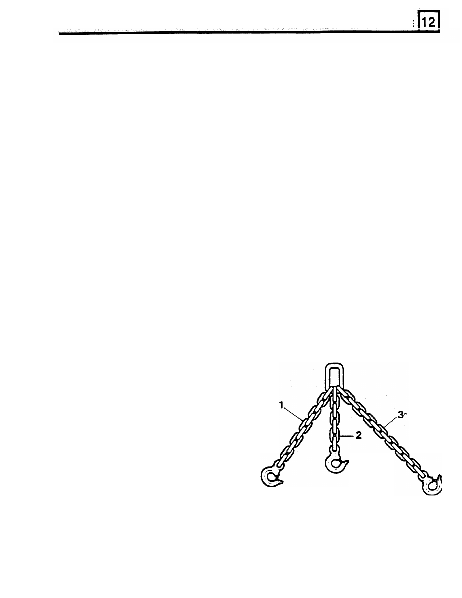
24.  Fit  lifting  chains  to  engine  lifting  eyes  as 

cooler  pipes 

to 

engine block. 

sides of  cylinder block. 

shown in illustration 

RR1780E. 

RRl780E 

1. 

L/H 

Front chain 356mm total overall  length. 

2. 

R/H Front chain 330mm 

total 

overall length. 

3. 

R/H  Rear chain 457mm total  overall  length 

ENGINE 

NOTE: All chain dimensions are measured from 

end of lifting hook to end of last link i n  chain. 

Refit 

43.  Fit  lifting chains 

to 

engine. Raise engine using 

25.  Fit chain  lifting eye to  a suitable engine hoist. 

hoist. 

Raise  hoist  high  enough  to  enable  engine 

44.  Lower  engine  into  engine  compartment. 

mountings  to  be  removed,  and  withdraw 

Ensure  all  components  are  clear  of  engine 

rubber mountings. 

assembly. 

26.  Lower  hoist  until  engine  rests  securely  on 

45.  Lower  engine  into  position.  Locate  primary 

engine  mounting  brackets.  Remove  lifting 

pinion  into  clutch.  Engage  bell  housing 

chains and hoist. 

dowels. 

27.  Disconnect two  heater hoses located on top of 

right hand rocker cover. 

47.  Remove  jack  and  lower  hoist  until  engine 

28.  Remove  ground  strap  from  rear  of  left  hand 

cylinder head.  DO NOT remove from retaining 

48.  Fit  top  two  bell  housing  securing  bolts. 

clip. 

Tighten to 40 Nm. 

29.  Remove all electrical harnesses from retaining 

clips at rear of engine. 

49.  Fit  remaining  bell  housing  to  cylinder  block 

30.  Remove  transmission  breather  pipes  from 

bolts, and tighten to 40 Nm. 

retaining clip on rear lifting eye. 

50.  Fit  new gasket and  refit bottom cover,  tighten 

31.  Remove top two  bolts securing bell housing to 

bolts to 9 Nm. 

cylinder block. 

51.  Fit  new exhaust flange  gaskets,  fit  exhaust  to 

32.  Raise front of  vehicle,  lower vehicle on to axle 

manifold. 

stands. 

52.  Refit  all  harnesses,  ground  straps  breather 

33.  Remove  bell  housing  bottom  cover.  Remove 

pipes and hoses at rear of engine. 

gasket from bell housing face. 

53.  Raise  engine  and  refit  engine  mounting 

34.  Remove  nuts  securing  exhaust  downpipes to 

rubbers, tighten nuts to 20 Nm. 

manifolds, remove heat shield from right hand 

54.  Remove  temporary  lifting  eye  ETC  5964  and 

side downpipe. 

reverse  instructions  1  to 23,  ensuring  that  all 

35.  Remove  electrical  leads  from  starter  motor 

electrical  plugs  and  harnesses  are  fitted  in 

solenoid.  Disconnect  multi-plug  from  oil  level 

correct locations. 

sensor on side of sump,  if fitted. 

36.  Remove  remaining  bell  housing  to  cylinder 

block bolts. 

37.  Remove  starter  motor  ground  strap  from 

chassis. 

38.  Remove stands and lower vehicle. 
39.  Position  hydraulic  trolley  jack  under  bell 

housing to  support  gearbox when engine and 
gearbox are separated. 

40.  Fit  lifting  chains  to  engine.  Carefully  raise 

hoist  a  little,  ease  engine  and gearbox  apart, 
steady engine on hoist. 

41.  Ensure  no  components  remain  that  will 

Prevent  engine  being  removed. 

42.  S l o w l y   raise  engine  clear  of  engine 

compartment.  Move engine away from vehicle 
and place on a suitable engine stand. 

46.  Fit two bolts and partially tighten. 

rests securely 

on engine mounting brackets. 

ENGINE 

ENGINE 

DISMANTLE AND  OVERHAUL 

Remove  engine  from  vehicle,  see  engine  removal 

and  clean  exterior.  For  safe  and  efficient  working 
secure  engine  to  an  approved  engine  stand.  Drain 

engine oil  into a suitable container. 

Remove intake manifold 

6. 

Lift  intake manifold from cylinder  heads. 

7.  Remove  surplus  coolant,  remove  gasket 

clamp bolts, remove clamps. 

8.  Lift off  gasket and seals. 

Remove exhaust manifolds 

1. 

Bend  back  lock  tabs,  remove  eight  bolts 

securing 

each 

manifold,  and 

withdraw 

1. 

Release hose clamp at water  pump 

manifolds and gaskets. 

2.  Detach retaining clips from top  of  injectors. 
3.  Remove  four  bolts  securing  fuel  rail  to 

manifold. 

4. 

Withdraw  fuel  rail and injectors. 

5. 

Evenly  loosen  and  remove  twelve  bolts 

securing intake manifold to cylinder  heads. 

Remove water pump 

1. 

Remove fifteen bolts, pump and joint washer. 

NOTE:  The  water  pump  is  not  serviceable.  II 

event 

of failure, fit a new water  pump assembly. 

RR1794E 

ENGINE 

REMOVE  AND  OVERHAUL 

ROCKER  SHAFTS 

Dismantle rocker shafts 

AND VALVE  GEAR 

5. 

Remove split  pin from one end 

of  rocker  shaft. 

1.  Remove  spark  plug  leads 

from  spark  plugs 

6.  Withdraw  following  components  and  retain  in 

and  retaining clips.  Release four  screws  and 

correct sequence for  re-assembly: 

lift 

off  rocker covers. 

7. 

A  plain washer. 

2.  Remove four  rocker  shaft  retaining 

bolts 

and 

8. 

A  wave washer. 

lift 

off  assembly. 

9. 

Rocker arms. 

10.  Brackets. 
11.  Springs. 
12.  Examine  each  component  for  wear,  in 

particular rockers and shafts.  Discard weak  or 
broken springs. 

3.  Withdraw  pushrods  and  retain  in  sequence 

removed. 

4.  Remove  hydraulic  tappets.  Retain  with  their 

respective  pushrods. 

If 

a  tappet  cannot  be 

removed  leave  in  position  until  camshaft  is 
removed. 

Inspect tappets and 

pushrods 

13.  Hydraulic  tappet:  inspect  inner  and  outer 

surfaces  of  body  for  blow  holes  and  scoring. 

Fit  a  new  hydraulic  tappet 

if 

body  is  roughly 

scored  or  grooved, 

or 

has  a  blow  hole 

extending  through wall  in a  position to  permit 
oil leakage from lower chamber. 

14.  The  prominent wear  pattern 

just  above  lower 

end  of  body  should  not 

be  considered  a 

defect unless it is definitely grooved or  scored. 

It  is  caused  by  side  thrust 

of 

cam  against 

body  while  tappet 

I

moving  vertically  in  its 

bore. 

15.  Inspect  cam  contact  surface  of  tappets.  Fit 

new  tappets 

if 

surface 

is 

excessively  worn 

or 

damaged. 

16.  A  hydraulic tappet body that  has been rotating 

will  have a  round wear  pattern. A  non-rotatlng 
tappet  body  will  have  a  square  wear  pattern 

with a very slight depression near centre. 

ST787M 


Content   ..  16  17  18  19   ..