Defender (1993+). Manual - part 19
RR750M
ENGINE
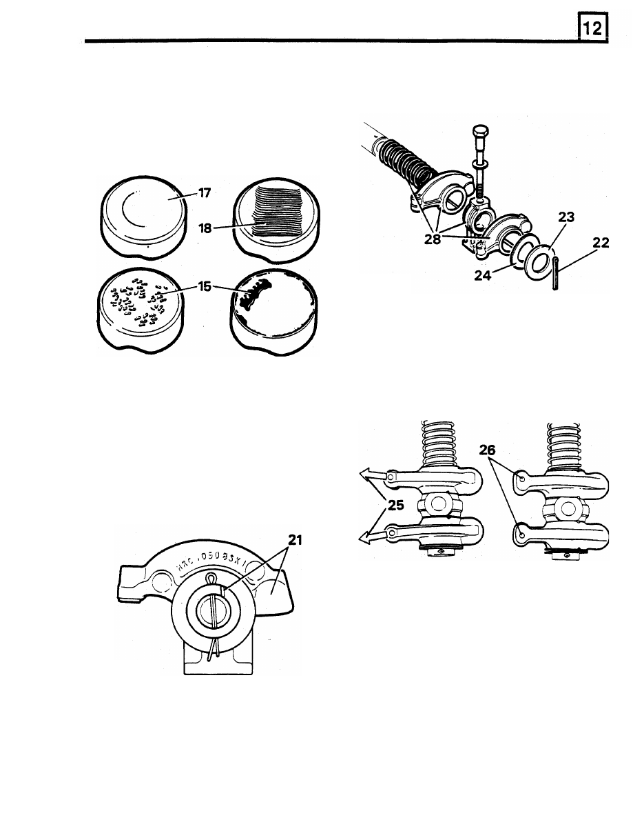
17.
Tappets MUST rotate, a circular wear
22. Fit new split pin to one end of rocker shaft.
condition
is
normal. Tappets with this wear
pattern can be refitted provided there are no
other defects.
18. If
a tappet is not rotating check camshaft
lobes for wear. Fit new tappet ensuring it
rotates freely in cylinder block.
23.
Slide
a plain washer over the long end
of
the
shaft to contact the split pin.
24.
Fit a wave washer to contact plain washer.
RR2937M
25.
Early type rocker arms are angled. They must
be fitted
so that valve end of rocker arms
angle away from each other as shown.
26.
On later type rocker arms the valve end
I
S
offset and must be fitted as shown.
27.
Early
and
late
rocker
arms
are
interchangeable provided complete set
is
changed.
19.
Fit a new hydraulic tappet
if
area of pushrod
contact is rough or damaged.
20. Fit a new pushrod
if
it is bent or has a rough
or damaged ball end
or seat.
Assemble rocker shafts
21.
Assemble rocker shafts with identification
groove at one o'clock position with push rod
end of rockers to the right.
RR2899M
28. Assemble rocker arms, brackets and springs
to rocker shaft.
29. Compress the springs, fit wave washer, plain
washer and split pin
to
end
of rocker shaft.
30.
Fit locating bolts through brackets. Place
assemblies
to
one side.
RR2900M
CAUTION:
If incorrectly assembled shafts
and rockers are fitted
to engine, oil supply
to
rocker shafts
will
be restricted.