Defender (1993+). Manual - part 16
ENGINE
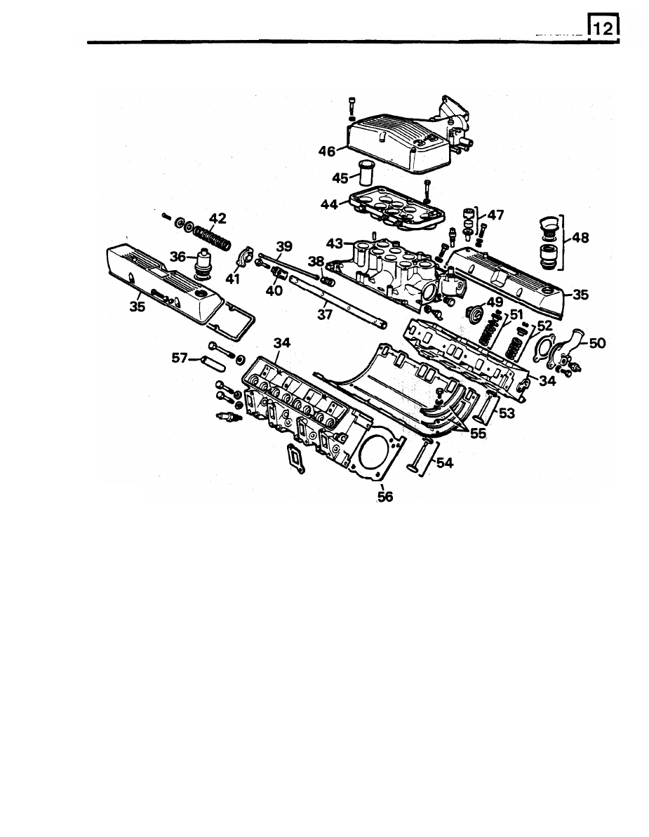
RR3524M
34. Cylinder heads (2)
46. Plenum chamber upper
35. Rocker covers (2)
47, Air filter
36. Oil separator
48. Oil filler
37. Rocker shafts (2)
49. Thermostat
38. Hydraulic tappets (8)
50. Thermostat cover
39. Pushrods (8)
51. Inlet valve spring, cap, seal
and
collets
(8)
40. Rocker brackets (8)
52. Exhaust valve spring, cap, collets
(8)
41. Rocker arms (4) left and
(4)
right
53. Inlet valve and seat (8)
42. Rocker shaft springs (6)
54. Exhaust valve and seat (8)
43. Inlet manifold
55. Tappet cover gasket and seals
44.
Plenum chamber lower
56. Cylinder head gaskets (2)
45. Ram pipes (8)
57. Valve guides (16)