Defender. Manual - part 92


  Index      Land Rover     Land Rover Defender - service manual 2007 year


Search            


Content   ..  90  91  92  93   ..


Defender. Manual - part 92


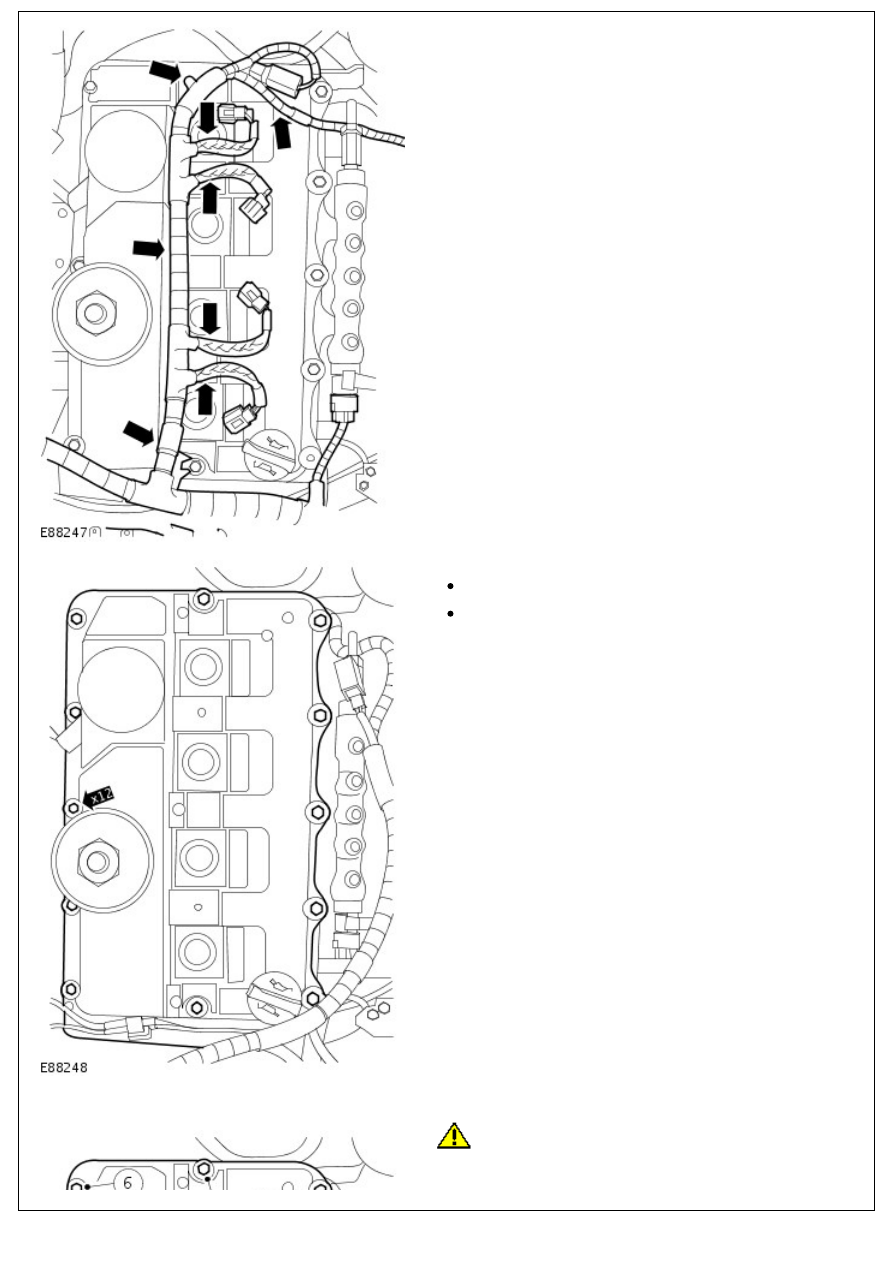
8. Release the engine wiring harness from the valve cover.

9. Remove the valve cover.

Fully loosen the 12 bolts.

Remove and discard the gasket.

Installation

1. 

CAUTION: Tighten the bolts in the sequence shown.

To install, reverse the removal procedure.

Install a new gasket.

Tighten the bolts to 10 Nm (7 lb.ft).

2. Connect the battery ground cable. 

For additional information, refer to: 

Battery Connect

 (414-01

Battery, Mounting and Cables, General Procedures).

Engine - 2.4L Duratorq-TDCi HPCR (103kW/140PS) - Puma - Engine

Removal

Removal

All vehicles

1. Disconnect the battery ground cable.

For additional information, refer to: 

Battery Disconnect and

Connect

 (414-01 Battery, Mounting and Cables, General

Procedures).

2. 

WARNING: Do not work on or under a vehicle

supported only by a jack. Always support the vehicle on safety

stands.

Raise and support the vehicle.

3. Remove the Hood. 

For additional information, refer to: 

Hood

 (501-02 Front End

Body Panels, Removal and Installation).

4. Remove the cooling fan shroud. 

For additional information, refer to: 

Cooling Fan Shroud

 (303-

03 Engine Cooling - 2.4L Duratorq-TDCi HPCR

(103kW/140PS) - Puma, Removal and Installation).

5. Remove the air cleaner. 

For additional information, refer to: 

Air Cleaner

 (303-12

Intake Air Distribution and Filtering - 2.4L Duratorq-TDCi

HPCR (103kW/140PS) - Puma, Removal and Installation).

6. Remove the catalytic converter. 

For additional information, refer to: 

Catalytic Converter

 (309-

00 Exhaust System - 2.4L Duratorq-TDCi HPCR

(103kW/140PS) - Puma, Removal and Installation).

7. Remove the starter motor. 

For additional information, refer to: 

Starter Motor

 (303-06

Starting System - 2.4L Duratorq-TDCi HPCR (103kW/140PS)

- Puma, Removal and Installation).

8. Release the crankshaft position (CKP) sensor and reverse

light switch wiring harness from the transmission.

Release the 3 clips.

9. Disconnect the reverse light switch electrical connector.

10. Release the reverse light switch wiring harness from the

transmission.

Release the clip.

11. Fully loosen the power steering pump lower 2 bolts.

12. Disconnect the coolant hose from the engine oil cooler.

Release the clip.

13. Disconnect the exhaust gas recirculation (EGR) cooler

coolant hose.

Release the clip.

Vehicles with air conditioning

14. 

CAUTION: Make sure that all openings are sealed.

Use new blanking caps.

Disconnect the air conditioning (A/C) high-pressure


Content   ..  90  91  92  93   ..