Defender. Manual - part 91


  Index      Land Rover     Land Rover Defender - service manual 2007 year


Search            


Content   ..  89  90  91  92   ..


Defender. Manual - part 91


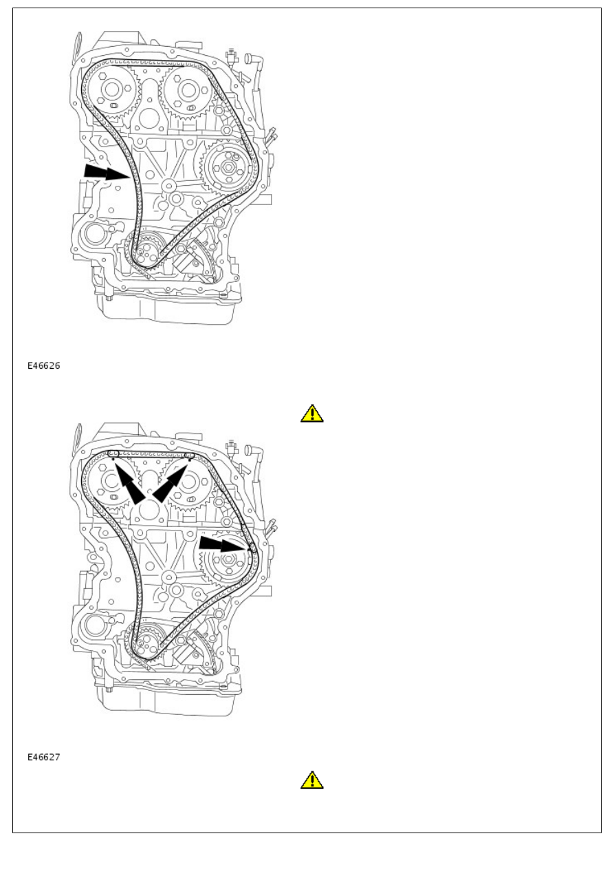
12. Remove the timing chain.

Installation

1. 

CAUTION: Make sure the colored links align to the

timing marks. Failure to follow this instruction may result in

damage to the vehicle.

Install the timing chain.

2. 

CAUTION: Make sure the timing chain tensioner is fully

retracted before installation. Failure to follow this instruction

may result in damage to the vehicle.

Install the timing chain tensioner and the timing chain guides.

Tighten the bolts to 15 Nm (11 lb.ft).

Tighten the nut to 15 Nm (11 lb.ft).

3. NOTE: Make sure the timing chain tensioner is completely

released.

Unlock the timing chain tensioner.

Remove the pin.

4. Secure the camshaft sprockets and the fuel injection pump

sprocket.

Tighten the camshaft sprocket bolts to 35 Nm (24 lb.ft).

Tighten the fuel injection sprocket bolts to 33 Nm (26

lb.ft).

5. Remove the special tool.
6. Remove the 6 mm bars.
7. Rotate the crankshaft clockwise 2 complete revolutions.

8. 

CAUTION: Make sure the special tool is fully located in

the flywheel.

Check the timing by inserting the special tool in the CKP

sensor hole.

9. Check the camshaft timing by inserting a suitable 6 mm bar

through the holes in the camshaft sprockets

10. Remove the special tool.
11. Remove the 6 mm bars.
12. Install the CKP sensor. 

For additional information, refer to: 

Crankshaft Position (CKP)

Sensor

 (303-14 Electronic Engine Controls - 2.4L Duratorq-

TDCi HPCR (103kW/140PS) - Puma, Removal and

Installation).

13. Install the timing cover. 

For additional information, refer to: 

Timing Cover

 (303-01

Engine - 2.4L Duratorq-TDCi HPCR (103kW/140PS) - Puma,

In-vehicle Repair).

14. Connect the battery ground cable. 

For additional information, refer to: 

Battery Connect

 (414-01

Battery, Mounting and Cables, General Procedures).

Engine - 2.4L Duratorq-TDCi HPCR (103kW/140PS) - Puma - Valve Cover

In-vehicle Repair

Removal

• WARNINGS:

 The spilling of fuel is unavoidable during this operation. Make sure that all necessary precautions are taken to

prevent fire and explosion.

 Do not carry or operate cellular phones when working on or near any fuel related components. Highly flammable

vapors are always present and may ignite. Failure to follow these instructions may result in personal injury.

 Do not smoke or carry lighted tobacco or open flame of any type when working on or near any fuel related

components. Highly flammable vapors are always present and may ignite. Failure to follow these instructions may result

in personal injury.

 If fuel contacts the eyes, flush the eyes with cold water or eyewash solution and seek immediate medical

attention.

 Wash hands thoroughly after fuel handling, as prolonged contact may cause irritation. Should irritation develop,

seek medical attention.

 Do not carry out any repairs to the fuel system with the engine running. The fuel pressure within the system can

be as high as 2000 bar (29,008 lb-sq-in). Failure to follow this instruction may result in personal injury.

CAUTION: Diesel fuel injection equipment is manufactured to very precise tolerances and fine clearances. It is

therefore essential that absolute cleanliness is observed when working with these components. Always install new

blanking plugs to any open orifices or lines. Failure to follow this instruction may result in foreign matter ingress to the

fuel injection system.

1. Disconnect the battery ground cable. 

For additional information, refer to: 

Battery Disconnect and

Connect

 (414-01 Battery, Mounting and Cables, General

Procedures).

2. Disconnect the positive crankcase ventilation (PCV) hose.

3. Remove the fuel injectors. 

For additional information, refer to: 

Fuel Injector

 (303-04A

Fuel Charging and Controls - 2.4L Duratorq-TDCi HPCR

(103kW/140PS) - Puma, Removal and Installation).

4. Release the fuel line.

4. Release the fuel line.

5. 

CAUTION: Make sure that all openings are sealed. Use

new blanking caps.

Disconnect the fuel return line.

6. 

CAUTION: Make sure that all openings are sealed. Use

new blanking caps.

Disconnect the fuel return line.

7. 

CAUTION: Make sure that all openings are sealed. Use

new blanking caps.

Remove the fuel return line.

8. Release the engine wiring harness from the valve cover.


Content   ..  89  90  91  92   ..