Defender. Manual - part 75
Item
Part Number
Description
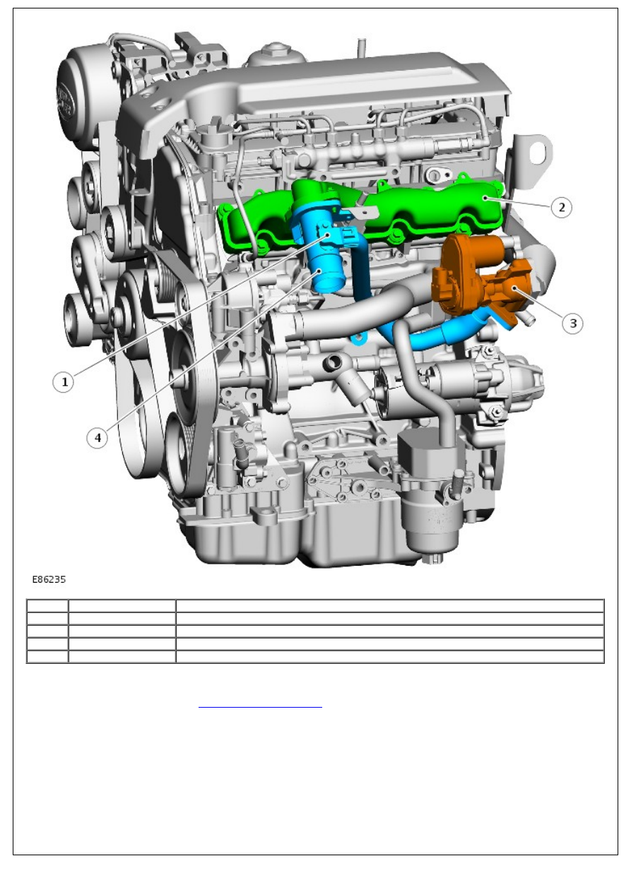
1
-
Mass Air Flow/Intake Air Temperature (MAF/IAT) sensor
2
-
Inlet manifold
3
-
EGR valve
4
-
EGR outlet assembly
The plastic inlet manifold is mounted on the LH side of the cylinder head and includes a connection for the EGR outlet
pipe. The EGR outlet pipe also houses the MAF/IAT sensor, which is used by the ECM to calculate the amount of air
entering the engine.
For additional information, refer to:
Electronic Engine Controls
(303-14 Electronic Engine Controls - 2.4L Duratorq-TDCi
HPCR (103kW/140PS) - Puma, Description and Operation).
Exhaust Manifold