Defender. Manual - part 76
Item
Part Number
Description
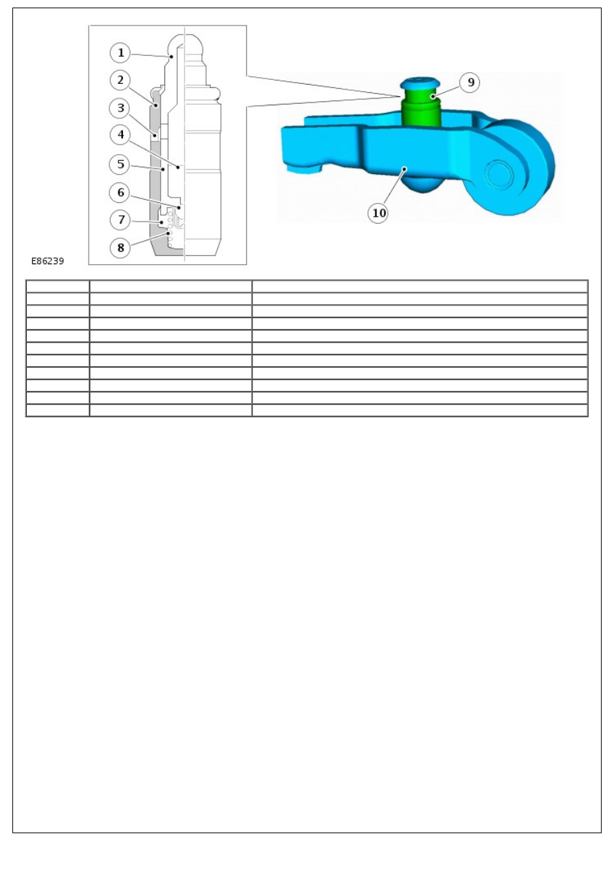
1
-
Plunger cap
2
-
Hydraulic lash adjuster body
3
-
Oil hole
4
-
Reservoir chamber
5
-
Plunger
6
-
Check ball
7
-
High-pressure chamber
8
-
Plunger spring
9
-
Hydraulic lash adjuster
10
-
Rocker arms
The body of the hydraulic lash adjuster contains a plunger and 2 chambers for oil feed and pressurised oil. The
pressurised oil is supplied to the adjusters via the main oil galleries in the cylinder head and through a hole in the side
of the adjuster body. The oil passes into a feed chamber in the adjuster and then through to a separate pressure
chamber via a 1-way ball valve.
Oil flow from the pressure chamber is determined by the amount of clearance between the adjuster outer body and the
centre plunger. Oil escapes up the side of the plunger every time the adjuster is operated, the downward pressure on
the plunger forcing a corresponding amount of oil in the adjuster body to be displaced. When the downward pressure
from the camshaft and finger rocker is removed (i.e. after the trailing flank of the camshaft lobe has passed), oil
pressure forces the adjuster's plunger up again. This pressure is not sufficient to effect the valve operation, but
eliminates the clearance between the finger rocker and top of the valve stem.
Camshaft Position (CMP) Sensor