Jeep Wrangler (2024 year). Manual in english - page 3
 

  Index      Manuals     Jeep Wrangler (2024 year). Manual in english


Search            copyright infringement  


Content      ..     1      2      3      4      ..


Jeep Wrangler (2024 year). Manual in english - page 3


LIGHTED CUPHOLDERS —
IF EQUIPPED

On some vehicles, the front cupholders are equipped
with a light ring that illuminates the cupholders for the
front passengers. The light ring is controlled by the dim-
mer control

page 72.

USB/AUX CONTROL

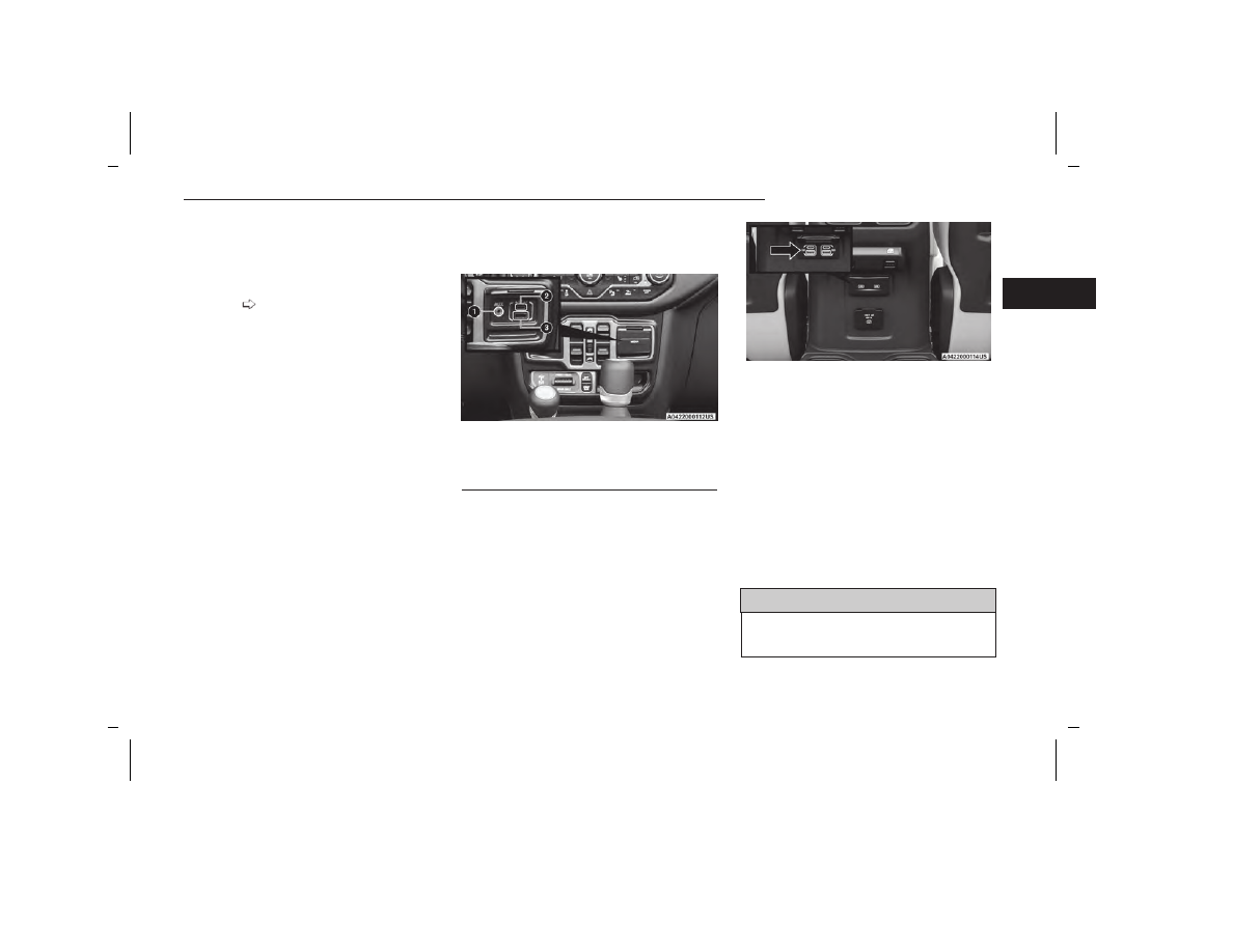
The Media Hub is located on the instrument panel,
below the climate controls. Behind the media hub
access door, the Media Hub contains one AUX port, a
Type C USB port and one standard USB port. Both USB
ports allow you to play music from MP3 players, smart-
phones or USB devices through the vehicle’s sound
system.

Plugging in a smartphone device to a USB port may
activate Android Auto™ or Apple CarPlay® features,
if equipped. For further information, refer to Android
Auto™ or Apple Carplay® in the Uconnect Radio Instruc-
tion Manual.

The Smart Charging USB ports provide power to your
device up to an hour after the vehicle is turned off.

NOTE:

Once a device is connected to the USB port, it will
begin charging and is ready for use with the system.
Type C and Type A charge-only USB ports can be
used at the same time but cannot be used simulta-
neously while playing media. When both Type C and
Type A charge-only USB ports are in use they will be
charged at a reduced rate.

Both ports share a single data connection. The user
cannot switch between Type A or Type C.

For example, if a device is plugged into the Type A USB
port and another device is plugged into the Type C USB
port, a message will appear and allow you to select
which device to use.

Located inside the center console, a second USB port
allows you to play music from USB devices through your
vehicle’s sound system.

Third and fourth USB ports (if equipped) are located
behind the center console, above the power inverter.
Both ports are charge only.

When a new device or smartphone is plugged into the
USB ports, the following message may display depend-
ing on the device being utilized:

“A new device is now connected. Previous connec-
tion was lost.”

“(Phone Name) now connected. Previous connection
was lost.”

“Another device is in use through the same USB
port. Please disconnect the first device to use the
second device.”

NOTE:

Charge unsupported devices with the Charge Only USB
ports. If an unsupported device is plugged into a Media
USB port, a message will display on the touchscreen
that the device is not supported by the system.

WARNING!

Do not plug in or remove the external device while
driving. Failure to follow this warning could result in a
collision.

Media Hub

1 — AUX Port
2 — Type C USB Port
3 — Type A USB Port

USB On The Back Of The Center Console

GETTING TO KNOW YOUR VEHICLE

79

2

5538906_24_JL_OM_EN_USC_t_E1.pdf   79

5/22/2023   9:02:20 AM

POWER OUTLETS

There are two 12 Volt (13 Amp) auxiliary power outlets
that can provide power for accessories designed for use
with the standard power outlet adapters.

The front power outlet is located in the center of the
instrument panel below the climate controls, and is
powered from the ignition switch. Power is available
when the ignition switch is in the ON/RUN or ACC
position.

On vehicles equipped with a rear subwoofer, there is a
second power outlet located in the rear cargo area and
is powered directly from the vehicle’s battery.

CAUTION!

Do not exceed the maximum power of 160 W
(13 Amp) at 12 Volt. If the 160 W (13 Amp) power
rating is exceeded, the fuse protecting the system
will need to be replaced.

Power outlets are designed for accessory plugs only.
Do not insert any other object in the power outlets
as this will damage the outlet and blow the fuse.
Improper use of the power outlet can cause damage
not covered by your New Vehicle Limited Warranty.

WARNING!

To avoid serious injury or death:

Do not insert any objects into the receptacles.

Do not touch with wet hands.

Close the lid when not in use.

If this outlet is mishandled, it may cause an elec-
tric shock and failure.

CAUTION!

Many accessories that can be plugged in draw
power from the vehicle's battery, even when not in
use (i.e., cellular phones, etc.). Eventually, if
plugged in long enough, the vehicle's battery will
discharge sufficiently to degrade battery life
and/or prevent the engine from starting.

Accessories that draw higher power (i.e., coolers,
vacuum cleaners, lights, etc.), will degrade the bat-
tery even more quickly. Only use these intermit-
tently and with greater caution.

(Continued)

Front Power Outlet

Rear Cargo Power Outlet

Power Outlets Fuse Locations

1 — F43 Fuse 20A Yellow Rear Power Outlet
(battery powered at all times)
2 — F45 Fuse 20A Yellow Rear Power Outlet
(powered when the ignition switch is in the ON/RUN or
ACC position)

80

GETTING TO KNOW YOUR VEHICLE

5538906_24_JL_OM_EN_USC_t_E1.pdf   80

5/22/2023   9:02:20 AM

CAUTION!

After the use of high power draw accessories, or
long periods of the vehicle not being started (with
accessories still plugged in), the vehicle must be
driven a sufficient length of time to allow the alter-
nator to recharge the vehicle's battery.

Power outlets are designed for accessory plugs
only. Do not hang any type of accessory or acces-
sory bracket from the plug. Improper use of the
power outlet can cause damage.

POWER INVERTER — IF EQUIPPED

There is a 115 Volt, 150 W inverter outlet located on
the back of the center console to convert DC current to
AC current.

This outlet can power cellular phones, electronics and
other low power devices requiring power up to 150 W.
Certain video game consoles exceed this power limit, as
will most power tools.

The power inverter is designed with built-in overload
protection. If the power rating of 150 W is exceeded,
the power inverter automatically shuts down. Once the
electrical device has been removed from the outlet, the
inverter should automatically reset. If the power rating
exceeds approximately 170 W, the power inverter may
have to be reset manually.

WARNING!

To avoid serious injury or death:

Do not insert any objects into the receptacles.

Do not touch with wet hands.

Close the lid when not in use.

If this outlet is mishandled, it may cause an elec-
tric shock and failure.

AUXILIARY SWITCHES —
IF EQUIPPED

Four auxiliary switches located in the lower switch bank
of the instrument panel can be used to power various
electrical devices. You have the ability to configure the
functionality of the auxiliary switches via the Uconnect
Settings

page 201.

All switches can be configured as follows:

Switch type operation:

Latching or Momentary

Power source:

Battery or Ignition

Ability to hold last state across key cycles:

On or Off

NOTE:

Holding last state conditions are met when switch type
is set to latching and power source is set to ignition.

The auxiliary switches manage the relays that power
four blunt cut wires. These wires are located under the
instrument panel in the passenger compartment and
under the hood to the right, near the battery.

Power Inverter

Auxiliary Switches

Auxiliary Switch Connections – Under Hood

GETTING TO KNOW YOUR VEHICLE

81

2

5538906_24_JL_OM_EN_USC_t_E1.pdf   81

5/22/2023   9:02:20 AM

In addition to the four auxiliary switch wires, a fused
battery wire and ignition wire are also located in the
interior, in the passenger side under the instrument
panel.

A kit of splices and heat shrink tubing are provided with
the auxiliary switches to aid in the connection/
installation of your electrical devices.

Wire Color Chart

Circuit

Function

Fuse

Wire

Color

Locations

Aux Switch 1

F93 –
40 Amp

Beige/
Pink

Interior (passen-
ger side under
instrument
panel) & Under-
hood (right side
near battery)

Circuit

Function

Fuse

Wire

Color

Locations

Aux Switch 2

F92 –
40 Amp

Green/
Pink

Interior (passen-
ger side under
instrument
panel) & Under-
hood (right side
near battery)

Aux Switch 3

F103 –
15 Amp

Orange/
Pink

Interior (passen-
ger side under
instrument
panel) & Under-
hood (right side
near battery)

Aux Switch 4

F108 –
15 Amp

Dark
Blue/
Pink

Interior (passen-
ger side under
instrument
panel) & Under-
hood (right side
near battery)

Battery

F72 –
10 Amp

Red/
White

Interior (passen-
ger side under
instrument
panel)

Ignition

F50 –
10 Amp

Pink/
Orange

Interior (passen-
ger side under
instrument
panel)

POWER WINDOWS — IF EQUIPPED

The power window switches are located on the instru-
ment panel below the climate controls. Push the switch
downward to open the window and upward to close the
window.

The top left switch controls the left front window and
the top right switch controls the right front window.

WARNING!

Never leave children unattended in a vehicle, and do
not let children play with power windows. Do not leave
the key fob in or near the vehicle, or in a location
accessible to children. Occupants, particularly unat-
tended children, can become entrapped by the win-
dows while operating the power window switches.
Such entrapment may result in serious injury or
death.

Auxiliary Switch Connections – Under Instrument Panel

Power Window Switches

82

GETTING TO KNOW YOUR VEHICLE

5538906_24_JL_OM_EN_USC_t_E1.pdf   82

5/22/2023   9:02:20 AM

To open the window part way (manually), push the win-
dow switch down briefly and release.

NOTE:

The power window switches will remain active for up to
10 minutes after ignition is placed in the OFF position.
Opening either front door will cancel this feature.

Four-Door Models

The lower left switch controls the left rear passenger
window, and the lower right switch controls the right
rear passenger window.

NOTE:

There are window switches located on the rear of the
center console for the rear passenger windows in the
four-door model.

AUTO-DOWN FEATURE

The driver door power and the passenger door power
window switches have an Auto-Down feature. Push the
window switch down to the second detent and release,
and the window will go down automatically.

To stop the window from going all the way down during
the Auto-Down operation, pull up on the switch briefly.

WARNING!

There is no anti-pinch protection when the window is
almost closed. Be sure to clear all objects from the
window before closing.

WINDOW LOCKOUT SWITCH

The window lockout switch allows you to disable the
window controls on the rear passenger doors. To dis-
able the window controls, rotate the switch downward.
To enable the window controls, rotate the switch
upward.

WIND BUFFETING

Wind buffeting can be described as the perception of
pressure on the ears or a helicopter-type sound in the
ears. Your vehicle may exhibit wind buffeting with the
windows down, or the Power Sliding Top (if equipped) in
certain open or partially open positions. This is a nor-
mal occurrence and can be minimized. If the buffeting
occurs with the rear windows open, open the front and
rear windows together to minimize the buffeting. If the
buffeting occurs with the sunroof open, adjust the sun-
roof opening to minimize the buffeting or open any
window.

WRANGLER TOPS

PROVIDED TOOLS

For your convenience, a tool kit is provided with your
vehicle located in the center console. This kit includes
the necessary tools required for the operations
described in the following sections. All pieces fit into the
ratchet for easy use.

NOTE:

The soft top and the hard top are to be used indepen-
dently.

Your vehicle warranty will not cover damage

resulting from both tops being installed at the same
time.

If your vehicle is equipped with a Dual Top (four door
models only), the soft top system will be provided in a
separate box located in the rear of the vehicle for ship-
ping purposes only.

Window Lockout Switch

Provided Tools

1 — Ratchet
2 — #T50 Torx Head Driver
3 — #T40 Torx Head Driver
4 — 15 mm Socket

GETTING TO KNOW YOUR VEHICLE

83

2

5538906_24_JL_OM_EN_USC_t_E1.pdf   83

5/22/2023   9:02:20 AM

LOWERING THE SOFT TOP INTO
SUNRIDER® POSITION

Use this QR code to access your digital
experience.

WARNING!

The fabric quarter windows and fabric top are
designed only for protection against the elements.
Do not rely on them to contain occupants within
the vehicle or to protect against injury during an
accident. Remember, always wear seat belts.

Make sure hands and fingers are clear of all pinch
points when installing and removing the soft tops.
The lift assist mechanism and side bows may
cause serious injury if fingers or hands get caught
in between.

CAUTION!

The soft top is not designed to carry any additional
loads such as roof racks, spare tires, building, hunt-
ing, or camping supplies, and/or luggage, etc. Also, it
was not designed as a structural member of the
vehicle and, thus, cannot properly carry any addi-
tional loads other than environmental (rain, snow,
etc.).

If the temperature is below 72°F (24°C) and/or the top
has been folded down for a period of time, the top will
appear to have shrunk when you raise it, making it diffi-
cult to put up. This is caused by a natural contraction of
the vinyl or acrylic materials of the fabric top.

Place the vehicle in a warm area. Pull steadily on the
top fabric. The vinyl will stretch back to its original size
and the top can then be installed.

If the temperature is

41°F (5°C) or below, do not attempt to put the top
down or roll the rear or side curtains.

CAUTION!

Do not run a fabric top through an automatic car
wash. Window scratches and wax buildup may
result.

Do not lower the top when the temperature is
below 41°F (5°C). Damage to the top may result.

(Continued)

CAUTION!

Do not move your vehicle until the top has been
either fully attached to the windshield frame, or
fully lowered.

Do not fully lower the top with the windows
installed. Window and top damage may occur.

For important information on cleaning and caring
for your vehicle's fabric top

page 336.

Do not use any tools (screwdrivers, etc.) to pry or
force any of the clamps, clips, or retainers securing
the soft top. Do not force or pry the soft top frame-
work when opening or closing. Damage to the top
may result.

Failure to follow these cautions may cause interior
water damage, stains or mildew on the top material:

It is recommended that the top be free of water
prior to opening it. Operating the top, opening a
door or lowering a window while the top is wet may
allow water to drip into the vehicle's interior.

Careless handling and storage of the soft top may
damage the seals, causing water to leak into the
vehicle's interior.

The soft top must be positioned properly to ensure
sealing. Improper installation can cause water to
leak into the vehicle's interior.

Scan me

84

GETTING TO KNOW YOUR VEHICLE

5538906_24_JL_OM_EN_USC_t_E1.pdf   84

5/22/2023   9:02:20 AM

Four Door Side View Components

1 — #1 Bow

6 — #6 Bow

2 — #2 Bow

7 — Front Window Retainer

3 — #3 Bow

8 — Lower Window Retainer

4 — #4 Bow

9 — Rear Quarter Window

5 — #5 Bow

GETTING TO KNOW YOUR VEHICLE

85

2

5538906_24_JL_OM_EN_USC_t_E1.pdf   85

5/22/2023   9:02:20 AM

Two Door Side View Components

1 — #1 Bow

6 — #6 Bow

2 — #2 Bow

7 — Front Window Retainer

3 — #3 Bow

8 — Lower Window Retainer

4 — #4 Bow

9 — Rear Quarter Window

5 — #5 Bow

86

GETTING TO KNOW YOUR VEHICLE

5538906_24_JL_OM_EN_USC_t_E1.pdf   86

5/22/2023   9:02:20 AM

Two And Four Door Rear Components

1 — Rear Window Retainer Attachment Points
2 — Quarter Window Pillars
3 — Swing Gate Bar Retainers

GETTING TO KNOW YOUR VEHICLE

87

2

5538906_24_JL_OM_EN_USC_t_E1.pdf   87

5/22/2023   9:02:20 AM

NOTE:

All lowering and raising the soft top instructions are
applicable to both two and four door model vehicles.

Images shown are of four door models, and appear-
ance of two door model components may differ.

The following options are available to you when lower-
ing your vehicle’s soft top:

Sunrider® position with rear and quarter windows
installed

Sunrider® position with rear and quarter panels
removed

Sunrider® position with rear window installed and
quarter panels removed

Fully lowered position with rear and quarter windows
removed

Both quarter windows should be removed and installed
together.

Lowering The Soft Top Into Sunrider® Position

1. Fold both sun visors forward against the windshield.

2. Release the header latches from the crossbar by

pulling the handle downward. Make sure the hook is
disengaged from its receiver.

3. From both the left and right sides, lift up on the

#1 Bow of the soft top to start the operation.

4. Move to the side of the vehicle and use the side link

to fold the soft top rearward into the Sunrider®
position.

NOTE:

If leaving the soft top in the Sunrider® position,
secure the top by using the two hook-and-loop fas-
teners provided in the center console.

NOTE:

The vehicle can be driven in the Sunrider® position
with the rear window and quarter panel assemblies
fully installed or completely removed.

The rear window and rear quarter windows

must

be

removed before fully lowering the soft top to prevent
damage to the top. Clean the side and rear windows
before removal to assist in preventing scratching
during removal of the soft top. If the plastic retain-
ers are difficult to operate due to road dust, etc.,
clean them with a mild soap solution and a small
brush. Cleaning products are available through an
authorized dealer.

Step Two

Step Three

Step Four

Step Four

88

GETTING TO KNOW YOUR VEHICLE

5538906_24_JL_OM_EN_USC_t_E1.pdf   88

5/22/2023   9:02:20 AM

Removing The Soft Top Windows

NOTE:

Before fully lowering the soft top, the rear window and
rear quarter windows

must

be removed.

Remove The Rear Window:

1. With the swing gate open, remove the rear window’s

plastic retainers from the lower right and left
corners.

2. Grab the swing gate bar, rotate it outward and

upward releasing it from both the right and left
retainers.

3. While holding the window in place, slide the swing

gate bar to the left separating it from the rear win-
dow. Store in soft window bag (if equipped), or a
safe location.

4. Remove the plastic retainers from both quarter win-

dow pillars.

5. While keeping the rear window level, slide to the left

until it is completely separate from its retainer.

Do

not pull downward while removing the rear window.
Damage to the retainer could result.

Step One

Step Two (Left Side Shown)

Step Three

Step Four

Step Five

GETTING TO KNOW YOUR VEHICLE

89

2

5538906_24_JL_OM_EN_USC_t_E1.pdf   89

5/22/2023   9:02:20 AM

Remove The Right And Left Quarter Windows:

1. Through the rear opening, push the bottom corner

outward and release tab from the bottom of the win-
dow pillar.

2. Undo the hook-and-loop fastener located at the

upper front corner of each quarter window.

3. Starting at the rear of the vehicle, remove plastic

retainer from along the bottom of the window mov-
ing toward the front of the vehicle.

4. Remove plastic retainer from the bottom to the top

of the front window.

5. While keeping the window level, slide rearward until

it is completely separate from its retainer.

Do not

pull downward while removing the window. Dam-
age to the retainer could result.

6. Store in soft window bag (if equipped) or a safe

location.

NOTE:

For information on the use of the storage bag, refer
to the next section.

Step One

Step Two

Step Three

Step Four

Step Five

90

GETTING TO KNOW YOUR VEHICLE

5538906_24_JL_OM_EN_USC_t_E1.pdf   90

5/22/2023   9:02:20 AM

Soft Top Window Storage Bag —

If Equipped

To safely store the soft top rear window, and rear quar-
ter windows, proceed as follows:

NOTE:

The swing gate bar, once removed from the rear win-
dow,

does not

store in the soft window storage bag

(if equipped).

1. With the bag opened completely, fold both fabric

dividers downward and lay the first quarter window
all the way to the right side with the inside of the
window facing downward and the window pillar to
the outside.

NOTE:

The quarter windows are marked “1” and “2” on the
inside of the window pillar.

2. Fold the first divider upward, covering the first quar-

ter window.

3. Lay the second quarter window on top of the first

divider all the way to the left side with the inside of
the window facing downward and the window pillar
to the outside.

4. Fold the second divider upward, covering the second

quarter window.

Step One

Step One

1 — Quarter Window Facing Downward
2 — Both Dividers Folded Down

Step Two

Step Three

1 — Quarter Window Facing Downward
2 — Second Divider Folded Down

Step Four

GETTING TO KNOW YOUR VEHICLE

91

2

5538906_24_JL_OM_EN_USC_t_E1.pdf   91

5/22/2023   9:02:20 AM

5. Lay the rear window on top of the second divider.

6. Close the storage bag and store in a safe location.

Lowering The Soft Top All The Way

1. Remove the rear window and quarter panel windows

page 89.

2. From the Sunrider® position

page 84, remove

straps if previously secured and move to the rear of
the vehicle.

3. Locate the Sunrider® latch beneath the #6 Bow of

the soft top on the left side.

4. Pull the latch to release the top, and allow the soft

top to slide rearward freely in the guide tracks to the
stowed position.

CAUTION!

Failure to follow the next steps could result in dam-
age to the Soft Top or vehicle.

5. While pushing downward slightly on the folded soft

top, slide the lock lever on the left and right side lift
assist mechanisms to the “lock” position.

6. Once the lock lever is in the “lock” position, push

downward on each side of the folded soft top to
ensure it is secure. An audible “click” may be heard.

Step Five

Step Six

Step Three

Step Four

Step Five (Locked Position)

92

GETTING TO KNOW YOUR VEHICLE

5538906_24_JL_OM_EN_USC_t_E1.pdf   92

5/22/2023   9:02:20 AM

NOTE:

Secure the top by using the two hook-and-loop fas-
teners provided in the center console.

RAISING THE SOFT TOP

Use this QR code to access your digital
experience.
Raising The Soft Top From The Fully
Lowered Position

1. From the fully lowered position,

remove straps if previously secured.

CAUTION!

Failure to follow the next steps could result in dam-
age to the Soft Top or vehicle.

2. While pushing down on the rear of the top, slide the

lock lever on the left and right side lift assist mecha-
nisms to the “unlock” position.

3. Push up and forward from the #5 Bow along the

guide track until it locks into the Sunrider® position
with an audible “click”.

4. Gently pull rearward on the #6 Bow to ensure the

top is locked in the Sunrider® position.

5. Using the side link, lift and push the soft top toward

the front of the vehicle manually guiding the top into
the closed position.

Step Six

Step Six

Scan me

Step Two

Step Three

1 — Unlocked Position
2 — #5 Bow Location

Step Five

GETTING TO KNOW YOUR VEHICLE

93

2

5538906_24_JL_OM_EN_USC_t_E1.pdf   93

5/22/2023   9:02:20 AM

6. From inside the vehicle, pull the handle on the

header latch downward to engage the hook into its
receiver. Repeat on the other side.

7. Pull the handle back upward while squeezing the

hook, locking the latch into place.

Installing The Soft Top Windows

Install The Right And Left Quarter Windows

1. From the rear of the vehicle, guide the top of the

window into the retainer and slide forward while
keeping the window level. Repeat on the other side.

2. Place the top of the quarter window pillar into the

top cover, and insert the bottom tab into the clip.

CAUTION!

Failure to follow all Quarter Window Install steps
could result in damage to the Soft Top or vehicle.

Step Five

Step Six

Step Seven

Step One

Step Two

Step Two

94

GETTING TO KNOW YOUR VEHICLE

5538906_24_JL_OM_EN_USC_t_E1.pdf   94

5/22/2023   9:02:20 AM

3. Engage the retainers on the front of the windows,

ensuring they are fully engaged, followed by the
retainers along the bottom of the windows.

NOTE:

It is

critical

that the retainers are fully engaged

before the vehicle resumes motion.

4. Secure the hook-and-loop fastener at the upper

front corner of each quarter window by pressing
firmly.

Install The Rear Window

1. Guide the rear window into the retainer from left to

right while keeping the window level.

2. Insert the swing gate bar into the retainers at the

bottom of the window from left to the right.

3. Rotate the swing gate bar into the left and right side

retainers.

4. Line up the rear window to the

right side

quarter

window first, and engage the plastic retainers.

Step Three

1 — Retainer At Front Of Quarter Window
2 — Retainer At Bottom Of Quarter Window

Step Four

Step One

Step Two

Step Three

GETTING TO KNOW YOUR VEHICLE

95

2

5538906_24_JL_OM_EN_USC_t_E1.pdf   95

5/22/2023   9:02:20 AM

5. Repeat with the left side quarter window.

6. Engage the rear window retainers in the lower right

and left corners.

NOTE:

For information on removing your soft top, refer to the
next section.

REMOVING THE SOFT TOP

Use this QR code to access your digital
experience.

1. Fully lower the soft top

page 92.

CAUTION!

Failure to follow the next steps could result in dam-
age to the Soft Top or vehicle.

2. Make sure the lift assist mechanism on both the left

and right sides are in the “lock” position, and an
audible “click” is heard when pushing down on the
#1 bow from each of the lift assist mechanisms
before removing.

3. Using the provided #40 Torx head driver and

ratchet, unscrew the two Torx head screws on each
lift assist mechanism, then lift the mechanism up
and away from the vehicle.

4. Pull the release lever on top of the rail rearward to

release the side link from the track.

Step Five

Step Six

Scan me

Step Two

Step Three

1 — Lock Position
2 — Torx Head Screw
3 — Torx Head Screw

Step Four

96

GETTING TO KNOW YOUR VEHICLE

5538906_24_JL_OM_EN_USC_t_E1.pdf   96

5/22/2023   9:02:20 AM

5. Repeat on the opposite side.

6. Utilizing two people, lift the soft top up and away

from the vehicle, careful to avoid the vehicle’s sport
bar, trim, and tire carrier. Store the soft top in a
safe, clean, and dry location.

7. Using the provided #50 Torx head driver and

ratchet, unscrew the Torx screw on both rear cor-
ners of the vehicle, removing the retainers.

INSTALLING THE SOFT TOP

1. If currently installed, remove the hard top

page 103.

2. Install the door rails, starting with the front, followed

by the rear on each side. For instructions and appro-
priate torque specifications for the door rail Torx
screws

page 111.

3. Install the rear retainers on each side of the rear of

the vehicle using the provided #50 Torx head driver
and ratchet. Refer to the following table for recom-
mended torque specifications.

CAUTION!

Do not overtighten Torx screws. Damage to the retain-
ers will occur.

Torque

Specification

For Torx Screw

Maximum

Minimum

119.5 in-lb

150.5 in-lb

106.2 in-lb

13.5 N·m

17.0 N·m

12.0 N·m

CAUTION!

Failure to follow the next steps could result in dam-
age to the Soft Top or vehicle.

Step Four

Step Six

Step Seven

Step Three

GETTING TO KNOW YOUR VEHICLE

97

2

5538906_24_JL_OM_EN_USC_t_E1.pdf   97

5/22/2023   9:02:20 AM

4. Making sure the lift assist mechanism is in the

“lock” position, lift the soft top into the rear of the
vehicle with the side links pointing toward the front.
Lower the lift assist mechanisms onto its retainers
on both sides (on the inside of the sport bar).

5. Using the provided #40 Torx head driver and

ratchet, tighten the Torx screws by turning them
clockwise. Secure them until they are snug (refer to
the following table for recommended torque specifi-
cations), being careful not to cross-thread the
screws or overtighten. Repeat on the opposite side.

Torque

Specification

For Torx Screws

Maximum

Minimum

119.5 in-lb

150.5 in-lb

106.2 in-lb

13.5 N·m

17.0 N·m

12.0 N·m

CAUTION!

Do not overtighten the screws. You can strip the
screws if they are overtightened.

6. While pulling the release lever on the top of the rail

rearward, place the side link into the guide track on
the top of the rail then release the lever.

7. Unsnap and remove the black boot cover. This cover

should be discarded. It was intended as a protective
cover for shipping only.

8. Raise the soft top

page 93.

NOTE:

Be sure the wire harness in the left rear corner is
not tangled in the soft top bows before you lift the
top.

Step Four

Step Four

Step Five

1 — Lock Position
2 — Torx Head Screw
3 — Torx Head Screw

Step Six

98

GETTING TO KNOW YOUR VEHICLE

5538906_24_JL_OM_EN_USC_t_E1.pdf   98

5/22/2023   9:02:20 AM

HARD TOP FRONT PANEL(S)
REMOVAL

CAUTION!

The hard top is not designed to carry any addi-
tional loads, such as after-market roof racks, spare
tires, building materials, hunting or camping sup-
plies, etc. For optional Mopar® accessory roof
racks

page 117.

Do not move your vehicle until the top has been
either fully attached to the front header, sport bar,
and body side or fully removed.

Failure to follow these cautions may cause interior
water damage, stains or mildew:

It is recommended that the top be free of water
prior to panel removal. Removing the top, opening
a door or lowering a window while the top is wet
may allow water to drip into the vehicle’s interior.

The hard top assembly must be positioned prop-
erly to ensure sealing. Improper installation can
cause water to leak into the vehicle’s interior.

Careless handling and storage of the removable
roof panels may damage the seals, causing water
to leak into the vehicle’s interior.

The front panel(s) must be positioned properly to
ensure sealing. Improper installation can cause
water to leak into the vehicle’s interior.

GETTING TO KNOW YOUR VEHICLE

99

2

5538906_24_JL_OM_EN_USC_t_E1.pdf   99

5/22/2023   9:02:20 AM

Four Door Hard Top Components

1 — Right Side Panel
2 — Left Side Panel
3 — Hard Top

100

GETTING TO KNOW YOUR VEHICLE

5538906_24_JL_OM_EN_USC_t_E1.pdf   100

5/22/2023   9:02:20 AM

Two Door Hard Top Components

1 — Right Side Panel
2 — Left Side Panel
3 — Hard Top

GETTING TO KNOW YOUR VEHICLE

101

2

5538906_24_JL_OM_EN_USC_t_E1.pdf   101

5/22/2023   9:02:20 AM

NOTE:

All hard top removal and installation instructions are
applicable to both two and four door model vehicles.

Images shown are of four door models, and appear-
ance of two door model components may differ.

The left side panel must be removed before remov-
ing the right side panel.

To remove the hard top front panel(s), proceed as
follows:

1. Fold down the sun visor against the windshield.

2. Turn the three L-shaped locks on the left side panel

(one at the front, the rear, and outside), unlocking
them from the roof.

3. Unlatch the left side header panel latch located at

the top of the windshield.

4. Remove the left side panel.

5. Repeat the previous steps to remove the right side

panel.

Hard Top Panel(s) Storage Bag —

If Equipped

The Freedom Top panels storage bag allows you to
store your hard top panels. The storage bag contains
two compartments.
Lay the bag for the Freedom Top panels down so the
loops and hooks are facing upward. Unzip the bag and
fold back the outer flap.

NOTE:

Ensure the front panel latch is closed prior to inserting
the panel into the panels bag.

1. Insert the left side hard top panel into the bag with

the latches facing upward.

2. Unfold the black panel divider (ensure the divider is

lying flat).

3. Insert the right side Freedom Top panel into the bag

with the latches facing downward.

NOTE:

Ensure the front panel latch is closed prior to insert-
ing the panel into the bag.

4. Unfold the outer flap and zip the hard top bag

closed.

5. Lift the Freedom Top bag into the vehicle with the

hooks and straps facing the back of the rear seat.
Attach the clip at the bottom of the bag to the child
restraint anchorage, located at the base of the rear
seat.

6. Wrap the upper strap around the rear head

restraints and loop the strap through the buckle.
Pull on the strap to tighten the Freedom Top bag
securely against the rear seat.

Step Two

Step Three

1 — Header Panel Latched
2 — Unlatched Position

Step Four

102

GETTING TO KNOW YOUR VEHICLE

5538906_24_JL_OM_EN_USC_t_E1.pdf   102

5/22/2023   9:02:20 AM

HARD TOP FRONT PANEL(S)
INSTALLATION

1. Open the header latch inside the vehicle, and the

three L-shaped locks on each panel.

2. Set the right side panel on the windshield frame

with the locating pin in the front receiver mounting
hole followed by the left side panel, making sure
there is no overhang. Also, make sure that the pan-
els are sitting flush with the body.

3. Reinstall the panel(s) using the same steps for

removal in reverse order.

NOTE:

To prevent water leaks, the seals and hard top panels
should be clear of any dust and debris prior to
reinstallation.

REMOVING THE HARD TOP

1. Remove both front panels

page 99.

2. Open both front doors.

3. Using the provided #50 Torx head driver and

ratchet, remove the two Torx head screws that
secure the hard top at the B-pillar (near the top of
the front doors).

4. Remove the six Torx head screws that secure the

hard top to the vehicle (along the interior bodyside —
three screws on each side) using the #50 Torx head
driver.

5. Open the swing gate all the way to ensure clearance

of the rear window glass. Lift the rear window glass.

6. Locate the wire harness and washer hose on the left

rear inside corner of the vehicle.

Step Three

Step Four

Step Five

Step Six

GETTING TO KNOW YOUR VEHICLE

103

2

5538906_24_JL_OM_EN_USC_t_E1.pdf   103

5/22/2023   9:02:20 AM

7. Release the locking tab by pushing it downward.

8. To remove the wiring harness, push the tab inward

while pulling downward to disconnect.

9. To remove the washer hose, push the release button

on hose connector, and pull downward.

10. Store the wire harness and washer hose in the

compartment below the trim. To access the stor-
age compartment, lift the trim cover as shown.

11. Secure the wire harness within the compartment

by plugging it into the receptacle and reengaging
the locking tab.

Step Seven

Step Eight

Step Eight

Step Nine

Step Ten

Step Eleven

104

GETTING TO KNOW YOUR VEHICLE

5538906_24_JL_OM_EN_USC_t_E1.pdf   104

5/22/2023   9:02:20 AM

12. Secure the washer hose by snapping it in next to

the receptacle, then replace the compartment
cover.

13. Lower the rear window, and close the swing gate.

14. Remove the hard top from the vehicle. Place the

hard top on a soft surface to prevent damage.

CAUTION!

The removal of the rear Hard Top requires four adults,
one located on each corner. Failure to follow this
caution could damage the Hard Top.

INSTALLING THE HARD TOP

If the door frames are installed from soft top usage,
they must be removed prior to installation of the hard
top. For removal procedures, see

page 110.

To install the hard top, place the hard top on the vehicle
while making sure that the top is sitting flush with the
body at the sides and check to ensure that there is a
uniform gap between the lift glass and hard top. Then
follow the removal steps in reverse order.

NOTE:

Inspect the hard top seals for damage and replace if
necessary.

The Torx fasteners that attach the hard top to the
body should be torqued as follows using the pro-
vided #50 Torx head driver and ratchet:

Hard top to B-pillar: 119 in-lb +/- 23 in-lb
(13.5 N·m +/- 2.7 N·m)

Hard top to J-rail: 154 in-lb +/- 30 in-lb (17.5 N·m
+/- 3.5 N·m)

SUNRIDER® FOR HARD TOP

WARNING!

Do not open or close the Sunrider® top while driving.
Operating the top while driving could cause the driver
to lose control of the vehicle. Failure to follow this
warning may result in serious injury or death.

The Sunrider® soft top can be used in place of the
Hard Top Freedom Panels for quick and easy opening of
the area above the driver and front passenger seats.

To install the Sunrider® soft top, proceed as follows:

1. Remove both front Hard Top Freedom panels

page 99.

2. With the help of a second person, set the Sunrider®

top onto the top of the vehicle making sure to align
the holes at the front and rear of the side rails.

Step Twelve

Sunrider® For Hard Top

Lower Sunrider® Onto The Vehicle

GETTING TO KNOW YOUR VEHICLE

105

2

5538906_24_JL_OM_EN_USC_t_E1.pdf   105

5/22/2023   9:02:20 AM

3. Swing the front frame bracket around the side of the

rail, and insert the door rail attachment bolt (pro-
vided bolt without spacer) from underneath. Tighten
with a #40 Torx head driver until snug.

4. Insert the rear door rail attachment bolt (provided

bolt with spacer) from underneath. Tighten with
#40 Torx head driver until snug.

5. Repeat steps 3 and 4 on the other side of the

vehicle.

NOTE:

The recommended torque specification for the front
and rear door rail attachment bolts is 8.8 ft-lb
(12 N·m).

6. Attach the rear clamp at the rear center of the

Sunrider® top using the two provided rear clamp
attachment bolts. Tighten with #40 Torx head driver
until snug.

NOTE:

The recommended torque specification for the rear
clamp attachment bolts is 3.7 ft-lb (5 N·m).

7. From inside the vehicle, lift and pull the Sunrider®

top forward using the integrated handle on the front
header of the top. Manually guide the top into the
closed position.

8. From inside the vehicle, pull the handle on the

header latch downward to engage the hook into its
receiver. Pull the handle back upward while squeez-
ing the hook, locking the latch into place. Repeat on
the other side.

Attach Front Door Rail Bolt

Attach Rear Door Rail Bolt

Rear Clamp Location

Push Sunrider® Top Forward

Engage Both Header Latches

106

GETTING TO KNOW YOUR VEHICLE

5538906_24_JL_OM_EN_USC_t_E1.pdf   106

5/22/2023   9:02:20 AM

To Open The Sunrider® Top

To open the Sunrider® top, proceed as follows:

1. Fold both sun visors forward against the windshield.

2. Release the header latches from the crossbar by

pulling the handle downward. Make sure the hook is
disengaged from its receiver.

3. From the front of the Sunrider® top, lift and push

the top rearward to the Sunrider® position.

4. Secure the top by using the two hook-and-loop fas-

teners provided with the Sunrider® kit, and wrap
one around the side rails on each side of the
Sunrider® top to hold it in place.

POWER SLIDING TOP —
IF EQUIPPED

CAUTION!

Lowering of the windshield is NOT recommended in
vehicles equipped with a Power Sliding Top. Damage
will occur to the top as well as the header seal.

If your vehicle is equipped with a Power Sliding Top, the
control switch can be found on the front trim panel, to
the right of the driver’s side sun visor.

NOTE:

The power top is non-removable. If desired, the rear
quarter windows can be removed and stored in the
provided storage bag

page 109.

The power top will not open in temperatures below
-4°F (-20°C). However, if it is opened at a higher
temperature, it can be closed at temperatures
above -40°F (-40°C).

The power top will not operate at vehicle speeds
above 60 mph (96 km/h).

NOTE:

A slight pause in audio may be heard when opening
and closing the Power Sliding Top as a result of the
Uconnect system switching between power top Closed
and power top Open audio modes.

Release Both Header Latches

Sunrider® Position

Hook-And-Loop Fastener Placement

Power Sliding Top Control Switch

1 — Open Switch
2 — Close Switch

GETTING TO KNOW YOUR VEHICLE

107

2

5538906_24_JL_OM_EN_USC_t_E1.pdf   107

5/22/2023   9:02:20 AM

WARNING!

Never leave children unattended in a vehicle, or
with access to an unlocked vehicle. Never leave
the key fob in or near the vehicle, or in a location
accessible to children. Do not leave the Keyless
Enter ‘n Go™ Ignition in the ACC or ON/RUN posi-
tion. Occupants, particularly unattended children,
can become entrapped by the power top while
operating the power top switch. Such entrapment
may result in serious injury or death.

In a collision, there is a greater risk of being thrown
from a vehicle with an open power top. You could
also be seriously injured or killed. Always fasten
your seat belt properly and make sure all passen-
gers are also properly secured.

Do not allow small children to operate the power
top. Never allow your fingers, other body parts, or
any object, to project through the power top open-
ing. Injury may result.

Opening And Closing The Power Top

Express Open/Close

Push the open switch and release it within one-half sec-
ond and the power top will open automatically from any
position. The power top will open fully and stop
automatically.

Push the close switch and release it within one-half
second and the power top will close automatically from
any position. The power top will close fully and stop
automatically.

During Express Open or Express Close operation, any
other movement of the power top switch will stop the
power top.

Manual Open/Close

To open the power top manually, push and hold the
open switch to the full open position, then release.

To close the power top manually, push and hold the
close switch to the fully closed position, then release.

Any release of the switch during open or close opera-
tion will stop the power top movement. The top will
remain in a partially opened position until the switch is
operated and held again.

Pinch Protect Feature

This feature will detect an obstruction in the opening of
the power top during Express Close operation. If an
obstruction in the path of the power top is detected, the
power top will automatically retract. Remove the
obstruction if this occurs. Next, push the close switch
and release to Express Close.

WARNING!

There is no anti-pinch protection when the power top
is almost closed. To avoid personal injury be sure to
clear your arms, hands, fingers and all objects from
the top’s path before closing.

NOTE:

The Power Sliding Top may reverse motion if closing
during a severe headwind. If this occurs, push and
hold the Power Sliding Top switch again to close the
top completely.

If three consecutive power top close attempts result
in Pinch Protect reversals, Pinch Protect will disable
and the power top must be closed in Manual Mode.

Power Top Maintenance

Use only a non-abrasive cleaner and a soft cloth to
clean the quarter window glass panel. For important
information on cleaning and caring for your vehicle

page 335.

Ignition Off Operation

The power top switch can remain active in Accessory
Delay for up to approximately 10 minutes after the vehi-
cle’s ignition is placed to the OFF position. Opening
either front door will cancel this feature.

NOTE:

Ignition Off time is programmable through the Uconnect
system

page 201.

Relearn Procedure

For vehicles equipped with a power top, there is a
relearn procedure that allows you to calibrate the power
top when the “Express Mode” stops working. To reset
the power top, follow these steps:

1. Place the ignition in the RUN position, and start the

vehicle.

NOTE:

The engine must be running to perform the relearn
procedure.

2. Ensure the power top is in the fully closed position.

3. Push and hold the Close switch for 10 seconds. This

will put the power top into calibration mode.

4. Continue holding down the close button while the

top goes fully open and then back to fully close.

108

GETTING TO KNOW YOUR VEHICLE

5538906_24_JL_OM_EN_USC_t_E1.pdf   108

5/22/2023   9:02:20 AM

5. Once the power top has stopped in the fully closed

position, release the close button. The power top is
now reset and ready to use.

NOTE:

If the close button is released anytime during the
relearning process, the relearn may not be complete,
and the procedure must be repeated.

Rear Quarter Window Removal

On vehicles equipped with a Power Sliding Top, the rear
quarter windows can be removed. To remove these win-
dows, follow this procedure:

1. Open the swing gate, and lift the rear window.

2. Open both side doors nearest the quarter windows.

3. Locate the rear quarter window latches (two on each

window) on the interior of the windows.

4. Rotate the left hand side latch

clockwise

to release.

5. Rotate the right hand side latch

counterclockwise

to

release.

6. From the outside of the vehicle, lift each window

upward and away from the vehicle.

NOTE:

Do not pull down or apply any weight to the windows
after the latches are released. Damage could result
to the pins holding the windows in place.

7. Store the rear quarter windows in the provided stor-

age bag and keep in a safe location, or securely fas-
ten the bag to the rear seat.

Quarter Window Storage Bag

To use the storage bags for the rear quarter windows,
proceed as follows:

1. With the bag completely open and the fabric divider

raised, place the first quarter window with the
latches facing outward into the foam insert. Fold
divider over the window once placed inside.

2. Place the second window into the foam insert with

the latches facing outward. Fully close the bag.

NOTE:

Once both windows are placed inside the bag, the
outside of the windows will be facing each other
with all latches facing the outside of the bag.

Step Five

1 — Rotate Left Handle Clockwise
2 — Rotate Right Handle Counterclockwise

Step Six

Step Six

Step One

1 — Bag Open With Divider Raised
2 — Lower Divider Over Window
(Latches Facing Outward)

GETTING TO KNOW YOUR VEHICLE

109

2

5538906_24_JL_OM_EN_USC_t_E1.pdf   109

5/22/2023   9:02:21 AM

3. Store the bag in a safe location, or in the cargo area

of the vehicle by securing the bag in the vehicle’s
cargo area. This is done by attaching the straps at
the top of the bag to the rear head restraints, as
well as attaching the clip at the bottom of the bag to
the forward most cargo hook on the load floor.

WARNING!

In a collision, unsecured rear quarter windows in the
vehicle could cause injury. They could fly around in a
sudden stop or rough terrain and strike someone in
the vehicle. Do not store the rear quarter windows in
the vehicle without securing them as instructed here.

DOOR FRAME

WARNING!

Do not drive your vehicle on public roads with the
door frame(s) removed as you will lose the protection
that they can provide. This procedure is furnished for
use during off-road operation only.

CAUTION!

Failure to follow these cautions may cause interior
water damage, stains or mildew:

Opening a door or lowering a window while the top
is wet may allow water to drip into the vehicle's
interior.

Careless handling and storage of the removable
door frame(s) may damage the seals, causing
water to leak into the vehicle's interior.

The door frame(s) must be positioned properly to
ensure sealing. Improper installation can cause
water to leak into the vehicle's interior.

DOOR FRAME REMOVAL

NOTE:

In four door models, the rear door frames must be
removed first, followed by the front door frames.

1. Using the provided #40 Torx head driver and

ratchet, loosen the Torx screws located on the
underside of each door frame (two per door).

2. Once all the way loosened, remove the screws by

pulling downward.

NOTE:

Screws will not fall out once completely loose, as
they are held in place by an internal mechanism.

Step Two

1 — Second Window Placed Over Divider
2 — Fully Closed Bag

Step Three

Door Frame Screw Locations

110

GETTING TO KNOW YOUR VEHICLE

5538906_24_JL_OM_EN_USC_t_E1.pdf   110

5/22/2023   9:02:21 AM


Content      ..     1      2      3      4      ..