Jeep Renegade (2022 year). Manual in english - page 4
 

  Index      Manuals     Jeep Renegade (2022 year). Manual in english


Search            copyright infringement  


Content      ..     2      3      4      5     ..


Jeep Renegade (2022 year). Manual in english - page 4


58


GETTING TO KNOW YOUR VEHICLE


L

OCK

/C

LOSE

 T

HE

 L

IFTGATE

To manually close the liftgate, grab the liftgate 

closing handle and pull in a downward motion to 

close the liftgate.

Closing Liftgate

NOTE:


Before closing the liftgate, make sure to be in 

possession of the key fob because the liftgate may 

be locked.
To Lock The Liftgate
With a valid Passive Entry key fob within 5


ft 

(1.5


m) of the liftgate, pushing the Keyless


Enter ‘n Go™ — Passive Entry lock button located to 

the right of the outside handle release will lock the 

vehicle.

NOTE:


The liftgate unlock feature is built into the elec

-

tronic liftgate release.

C

ARGO

 A

REA

 F

EATURES

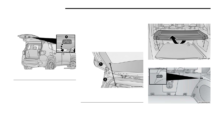
Removable Rear Shelf — If Equipped
To remove rear shelf, proceed as follows:
1. Disconnect the two links that support the 

shelf at the eyelets.

Rear Shelf Support Links

2. Lift the rear part of the overhead luggage shelf.
3. Clear the pins placed outside of the shelf, and 

then remove the rear shelf pulling it upwards.

4. The rear shelf can be stored in the cargo area, 

or behind the front seatbacks.

Adjusting The Rear Shelf

Rear Shelf Pin

Cargo Load Floor
The vehicle is equipped with a load floor that can 

be adjusted as needed.

1 — Liftgate Pull Handle

1 — Eyelets
2 — Links


GETTING TO KNOW YOUR VEHICLE


59

Position 1 (Lowered Position):
This position allows you to make the load floor flat 

for ease of loading/unloading objects from the 

cargo area. This position also makes it possible to 

use the space below as another compartment for 

storing fragile or smaller objects.
Position 2 (Elevated Position):
When the rear seatbacks and front passenger seat 

are folded flat, it creates space for objects of long 

dimensions. This position is recommended only 

when transporting objects, then move the load 

floor back to position 1.
Table Tilt Load
In addition to the two positions described 

previously, the load floor can also be placed in a 

tilted position, slanted toward the rear seatbacks 

as to ease the access to the underlying zone of the 

luggage compartment (e.g. to pick up the spare tire 

or the Tire Service Kit).
Place the load floor in a way that it rests at the 

supports 1 and 2 on the sides of the cargo area.
The load floor provides securing of any cargo inside 

this position, so that the cargo will not slide in the 

case of sudden braking.

Load Floor

Table Tilt Load Supports

Access To The Loading Floor
To access the double load compartment, proceed 

as follows:
1. Lift up on the Load Floor Handle.

Load Floor Handle

2. Place the desired objects inside the 

compartment.

1 — Loading Floor Support One
2 — Loading Floor Support Two

2

60


GETTING TO KNOW YOUR VEHICLE


3. Reposition the load floor.

Cargo Area Storage

Displacement Load Floor
To position the load floor from the lower to the 

upper position, proceed as follows:
1. Grab the load floor handle and lift up the load 

floor.

2. Correctly place the load floor on the side panel 

guides and on the rear cross member.

Access To Tire Service Kit Or Spare Tire
To access the Tire Service Kit or spare tire and 

container carrier, proceed as follows:
1. Grab the load floor handle and remove the 

floor.

2. Pull the tab and lift up on the carpet.

Anchoring Of The Load
The cargo tie-downs, located on the cargo area 

floor, should be used to safely secure loads when 

the vehicle is moving.

Tie-Downs

The side panels may be equipped with three 

grocery hooks (one on the left side and two on the 

right side) for securing loads that are not 

excessively heavy.

Grocery Hook

Grocery Hooks

CAUTION!


The load floor must be arranged in a central 

position with respect to cargo area.


GETTING TO KNOW YOUR VEHICLE


61

Cargo Box — If Equipped

The cargo area contains a preformed cargo box 

that can be used for the storage of objects that 

allows you to obtain a uniform level when loading.

Cargo Box

NOTE:


The cargo box is sized for a maximum capacity of 

distributed weight equal to 242 lb (110 kg).

ROOF LUGGAGE RACK — IF EQUIPPED 

Your vehicle may be equipped with a Roof Luggage 

Rack for transporting accessories.
Crossbars should always be used whenever cargo 

is placed on the Roof Luggage Rack. Check the 

straps frequently to be sure that the load remains 

securely attached.

NOTE:


Crossbars can be purchased at an authorized 

dealer through Mopar® parts. External racks do 

not increase the total load carrying capacity of the 

vehicle. Be sure that the total occupant and 

luggage load inside the vehicle, plus the load on 

the Roof Luggage Rack, do not exceed the 

maximum vehicle load capacity.
The load carried on the roof, when equipped with a 

luggage rack, must not exceed 150 lb (68 kg), and 

it should be uniformly distributed over the cargo 

area.
Do not use the retractable roof when using the 

crossbars.

WARNING!


Cargo must be securely tied down before driving 

your vehicle. Improperly secured loads can fly off 

the vehicle, particularly at high speeds, resulting 

in personal injury or property damage. Follow 

the roof rack cautions when carrying cargo on 

your roof rack.

CAUTION!


To avoid damage to the roof rack and vehicle, 

do not exceed the maximum roof rack load 

capacity. Always distribute heavy loads as 

evenly as possible and secure the load appro

-

priately.

Long loads, which extend over the windshield, 

should be secured to both the front and rear of 

the vehicle.

Place a blanket or other protection between 

the surface of the roof and the load.

Travel at reduced speeds and turn corners 

carefully when carrying large or heavy loads 

on the roof rack. Wind forces, due to natural 

causes or nearby truck traffic, can add sudden 

upward lift. It is recommended to not carry 

large flat loads, such as wood panels or surf

-

boards, which may result in damage to the 

cargo or your vehicle.

Load should always be secured to crossbars 

first, with tie down loops used as additional 

securing points if needed. Tie loops are 

intended as supplementary tie down points 

only. Do not use ratcheting mechanisms with 

the tie loops. Check the straps frequently to be 

sure that the load remains securely attached.

2

62


GETTING TO KNOW YOUR INSTRUMENT PANEL

INSTRUMENT CLUSTER


GETTING TO KNOW YOUR INSTRUMENT PANEL


63

3

64


GETTING TO KNOW YOUR INSTRUMENT PANEL


I

NSTRUMENT

 C

LUSTER

 D

ESCRIPTIONS

1. Tachometer

Indicates the engine speed in revolutions 

per minute (RPM x 1000).

2. Instrument Cluster Display

The instrument cluster display features a 

driver interactive display  

Ú


page


64.

3. Speedometer

Indicates vehicle speed.

4. Temperature Gauge

The temperature gauge shows engine 

coolant temperature. Any reading within the 

normal range indicates that the engine 

cooling system is operating satisfactorily.

The gauge will likely indicate a higher 

temperature when driving in hot weather or 

up mountain grades. It should not be 

allowed to exceed the upper limits of the 

normal operating range.

5. Fuel Gauge

The fuel gauge shows the level of fuel in the 

fuel tank when the ignition is in the ON/RUN 

position.

 The fuel pump symbol points to the 

side of the vehicle where the fuel 

door is located.

INSTRUMENT CLUSTER DISPLAY 

Your vehicle is equipped with an instrument cluster 

display, which offers useful information to the 

driver. With the ignition in the OFF position, 

opening/closing of a door will activate the display 

for viewing, and display the total miles, or 

kilometers, in the odometer. Your instrument 

cluster display is designed to display important 

information about your vehicle’s systems and 

features. Using a driver interactive display located 

on the instrument panel, your instrument cluster 

display can show you how systems are working and 

give you warnings when they aren’t. The steering 

wheel mounted controls allow you to scroll through 

and enter the main menus and submenus. You can 

access the specific information you want and 

make selections and adjustments.

I

NSTRUMENT

 C

LUSTER

 D

ISPLAY


L

OCATION

 A

ND

 C

ONTROLS

The instrument cluster display features a driver 

interactive display that is located in the instrument 

cluster.

Instrument Cluster Display Location

WARNING!


A hot engine cooling system is dangerous. You or 

others could be badly burned by steam or boiling 

coolant. You may want to call an authorized 

dealer for service if your vehicle overheats.

CAUTION!


Driving with a hot engine cooling system could 

damage your vehicle. If the temperature gauge 

reads “H” pull over and stop the vehicle. Idle the 

vehicle with the air conditioner turned off until 

the pointer drops back into the normal range. If 

the pointer remains on the “H”, turn the engine 

off immediately and call an authorized dealer for 

service.

1 — Instrument Cluster Display Locations
2 — Instrument Cluster Display Controls


GETTING TO KNOW YOUR INSTRUMENT PANEL


65

Setting the system allows the driver to select 

information by pushing the following buttons 

mounted on the steering wheel:

Instrument Cluster Display Control Buttons

Left Arrow Button 
Push the left arrow button to return to the main 

menu from an info screen or submenu item.

Up Arrow Button 
Push and release the up arrow button to scroll 

upward through the main menu.

Right Arrow Button 
Push and release the right arrow button to 

access the information screens or submenu 

screens of a main menu item.

Down Arrow Button 
Push and release the down arrow button to 

scroll downward through the main menu.

OK Button 
Push the OK button to access/select the infor

-

mation screens or submenu screens of a main 

menu item. Push and hold the OK button for one 

second to reset displayed/selected features 

that can be reset.

O

IL

 C

HANGE

 R

ESET


Oil Change Due
Your vehicle is equipped with an engine oil change 

indicator system. The “Oil Change Due” message 

will display in the instrument cluster display for five 

seconds after a single chime has sounded to 

indicate the next scheduled oil change interval. 

The engine oil change indicator system is duty 

cycle based, which means the engine oil change 

interval may fluctuate, dependent upon your 

personal driving style.

Unless reset, this message will continue to display 

each time the ignition is cycled to the ON or RUN 

position. To reset the oil change indicator system 

(after performing the scheduled maintenance), 

refer to the following procedure:
1. Without pushing the brake pedal, push the 

ENGINE START/STOP button and cycle the 

ignition to the ON/RUN position (do not start 

the engine).

2. Fully push the accelerator pedal, slowly, three 

times within 10 seconds.

3. Without pushing the brake pedal, push the 

ENGINE START/STOP button once to return the 

ignition to the OFF position.

NOTE:


If the indicator message illuminates when you start 

the vehicle, the oil change indicator system did not 

reset. See an authorized dealer to have the oil life 

reset.

1 — Left Arrow Button
2 — Up Arrow Button
3 — Right Arrow Button
4 — Down Arrow Button
5 — OK Button

3

66


GETTING TO KNOW YOUR INSTRUMENT PANEL


I

NSTRUMENT

 C

LUSTER

 D

ISPLAY

 M

ENU


I

TEMS


NOTE:


The instrument cluster display menu items display 

in the center of the instrument cluster. Menu items 

may vary depending on your vehicle features.

Speedometer

Push and release the up   or down   arrow 

button until the speedometer is displayed in the 

instrument cluster display. Push and release the 

OK button to toggle units (mph or km/h) of the 

speedometer.

Vehicle Info

Push and release the up   or down   arrow 

button until “Vehicle Info” is highlighted in the 

instrument cluster display. Push and release the 

right   arrow button and Coolant Temp will be 

displayed. Push the right   or left   arrow button 

to scroll through the following information displays:

Tire Pressure — View the information relating to 

the Tire Pressure Monitoring System (If 

Equipped).

Coolant Temperature — View the engine coolant 

temperature.

Trans Temperature — View the trans oil 

temperature.

Oil Temperature — View the oil temperature.

Battery Voltage — View the voltage value (state 

of charge) of the battery.

Service — View the service status message(s) (If 

Equipped).

Driver Assist — If Equipped

Push and release the up   or down   arrow 

button until the Driver Assist menu title displayed 

is highlighted in the instrument cluster display.
LaneSense — If Equipped
The instrument cluster display displays the current 

LaneSense status and information. The 

information displayed depends on LaneSense 

system status and the conditions that need to be 

met  

Ú


page


133.

Fuel Economy

This menu item allows you to view the fuel 

economy of the vehicle. The following will display:

Range (Miles or km)

Current Consumption (mpg or L/100 km or 


km/L)

Average Consumption (mpg or L/100 km or 


km/L)

Reset procedure shown at the bottom of the 

display.

Trip Info

Push and release the up   or down   arrow 

button until the Trip menu title is displayed in the 

instrument cluster display. Toggle the left   or 

right   arrow button to select Trip A or Trip B. The 

Trip information will display the following:

Distance – Shows the total distance (mi or km) 

traveled for Trip A or Trip B since the last reset.

Average Fuel Economy – Shows the average 

fuel economy (MPG or L/100


km or km/L) of 

Trip A or Trip B since the last reset.

Elapsed Time – Shows the total elapsed time of 

travel since Trip A or Trip B has been reset.

Hold the OK button to reset feature information.

Stop/Start – If Equipped

Push and release the up   or down   arrow 

button until the Stop/Start menu title is displayed 

in the instrument cluster display.
This menu shows messages related to Stop/Start. 

Only one message can be viewed at a time until the 

condition is cleared. When the Stop/Start is 

engaged (and the engine is off), the associated 

hardware telltale is turned on. Whenever a user 

pushes the Stop/Start button on the central stack, 

a pop-up message of the Stop/Start status will 

appear on the instrument cluster display.


GETTING TO KNOW YOUR INSTRUMENT PANEL


67

Audio

Push and release the up   or down   arrow 

button until the Audio menu title is displayed in the 

instrument cluster display.

Stored Messages

Push and release the up   or down   arrow 

button until the Messages Menu Icon is highlighted 

in the instrument cluster display. This feature 

shows the number of stored warning messages. 

Pushing the left   or right   arrow button will 

allow you to scroll through the stored messages.

Screen Setup

This menu item allows you to change the position 

of the information on the display.
Display Gears (Vehicles With Reconfigurable 

Multi-Functional Display And Automatic 

Transmission)
By selecting this item, you can select the display 

mode, the particulars relating to the automatic 

transmission, and choose between the following 

options:

“Single digit” 
The right side of the display will show the letter 

concerning the automatic transmission gear 

selector (P,R,N or D) position. After approxi

-

mately two seconds, the letter will be displayed 

in a central position.

“Full PRND” 
The letters PRND will display on the right side, 

the position assumed by the gear selector will 

be highlighted in the display. During the opera

-

tion in sequential mode (“AutoStick”), in place 

of the letter D, the gear will be will be displayed.

In The Upper Left/Top Right
The information relating to the following can be 

displayed:

External temperature

Ignition Button — If Equipped

Compass — If Equipped

Date (Month/Day)

Time (Hours/Minutes)

In the central area of the display, you can view all 

of the information listed above as well as the 

following:

Compass — If Equipped

Speed Display — If Equipped

Date (Day/Month/Year)

Time

Compass — If Equipped

Ignition Button — If Equipped

External Temp — If equipped

Menu Item

Distance Traveled A (Trip A)

Distance Traveled B (Trip B)

Restore Default Settings
Selecting this item, and you can reset and restore 

the default settings.

Settings

This menu item allows you to change the settings 

for the following:

Display

Units

Clock and Date

Security

Safety and Assistance

Lights

Doors and Locks

NOTE:


Some items may be displayed and managed 

through the Uconnect system.
Vehicles Equipped With Multi-functional Display 

Reconfigurable:
The following menu/submenu items are available 

in the cluster display.

3

68


GETTING TO KNOW YOUR INSTRUMENT PANEL


“Vehicle Shut Off (If Equipped)”
By selecting the item “Vehicle Shut Off”, you can 

turn off the engine from the instrument cluster. 

This feature is available in the event of an ignition 

switch failure, and will display instructions for 

turning off the engine via the instrument cluster 

display controls.
“Display”
By selecting the “Display,” you can access the 

following setting:

Language: allows you to select the language in 

which to display the information/warnings.

“Units Of Measure”
By selecting the item “Units of Measure,” you can 

select the unit of measure to use for displaying 

various magnitudes.
Possible options are:

US

Metric

Custom

“Clock & Date”
By selecting the item, “Clock & Date” you can 

adjust the clock.
Possible options are:

Set Time: adjust hours/minutes

Set Format: adjust the time format “12h” 


(12 hours) or “24h” (24 hours)

Set Date: adjust day/month/year

“Security”
By selecting the item “Security,” you can make the 

following adjustments:

Speed Warning: 
Set the vehicle speed limit, which the driver is 

notified through a visual and acoustic signaling 

(display of a message and a symbol on the 

display).
When the speed warning is set, the icon should 

remain visualized for the same duration time of 

the pop-up. If the driver exceeded the set speed, 

the icon should remain for however long the 

vehicle is over the set speed.
Driver may also turn the Speed Warning “OFF” 

should you choose not to use this feature.

Seat Belt Reminder: 
This function is only viewable when the Seat Belt 

Reminder (SBR) system is active.

Hill Start Assist: 
Activation/Deactivation of the Hill Start Assist 

system.

Passenger Air Bag — If Equipped 
Front passenger air bag may be enabled or 

disabled.

“Lights”
By selecting the item “Lights,” you can make the 

following adjustments:

Headlight Off Delay: set the delay for headlight 

shutoff after engine shutoff

Headlight Sensitivity: adjust the sensitivity of 

headlight brightness

Daytime Running Lights: activate/deactivate 

the daytime running lights

Cornering lights: activate/deactivate the 

cornering lights (If Equipped)

Interior Ambient lights: adjust the level of inte

-

rior ambient lights

Greeting Lights: activate / deactivate greeting 

lights

“Doors & Locks”
By selecting the item “Doors & Locks,” you can 

make the following adjustments:

Auto Door Lock: activate/deactivate the auto

-

matic locking of the doors with the vehicle 

moving

Auto Unlock On Exit: automatic unlocking of the 

doors when exiting the vehicle

Flash Light with Lock: activate the direction indi

-

cators when closing the doors


GETTING TO KNOW YOUR INSTRUMENT PANEL


69

Sound Horn With Lock: activate/deactivate the 

horn when pushing the LOCK button on the key 

fob. The options are “Off,” “First Press,” and 

“Second Press”

Horn With Remote Start: activate/deactivate 

the horn at the Remote Starting of the engine 

with the key fob

Remote Door Unlock: allows you to open the 

driver door only on the first push of the UNLOCK 

button on the key fob

“Compass”
By selecting the item “Compass” you can make the 

following adjustments:

Compass Calibration

Compass Variance

TRIP COMPUTER

The Trip computer is used to display information on 

car operation when the key is turned to the RUN 

position.
This function allows you to define two separate 

trips called “Trip A” and “Trip B” where the car's 

“complete trips” are monitored in an independent 

manner.
Both trips can be reset (reset - start of a new trip). 

To perform a reset, push and hold the OK button on 

the steering wheel controls.

“Trip A” and “Trip B” are used to display the figures 

relating to:

Distance Traveled

Average Consumption

Travel Time (driving time)

Quantities Displayed
Distance Traveled

Indicates the distance traveled by the start of 

the new trip.

Average Consumption

Represents the average fuel consumption since 

the start of the new trip.

Travel Time

Elapsed time since the start of the new trip.

OK Button
Short Push Of The Button: display of various 

parameters.
Long Push Of The Button: reset quantities and 

begin a new trip.
New trip
Starts after reset:

“Manual” by pushing the OK button.

“Automatic” when the “distance” reaches the 

value of 62140 (99999.9


km) or when the 

“time travel” reaches the value of 999.59 


(999 hours and 59


minutes).

After each disconnection and reconnection of 

the battery.

WARNING/INDICATOR LIGHTS AND 

MESSAGES

The warning/indicator light switches on in the 

instrument panel together with a dedicated 

message and/or acoustic signal when applicable. 

These indications are indicative and precautionary 

and as such must not be considered as exhaustive 

and/or alternative to the information contained in 

the Owner Manual, which you are advised to read 

carefully in all cases. Always refer to the 

information in this chapter in the event of a failure 

indication.
All active telltales will display first, if applicable. 

The system check menu may appear different 

based upon equipment options and current vehicle 

status. Some telltales are optional and may not 

appear.
The following warning lamps and indicators will 

alert you to a vehicle condition that may become 

serious. Some lamps will illuminate when you start 

your vehicle to make sure they work. If any lamps 

remain on after starting your vehicle, refer to the 

respective system warning lamp for further 

information.

3

70


GETTING TO KNOW YOUR INSTRUMENT PANEL


R

ED

 W

ARNING

 L

IGHTS

Air Bag Warning Light  

This light will turn on for four to eight 

seconds as a bulb check when the 

ignition is placed in the ON/RUN or MAR/

ON/RUN position. If the light is either not 

on during startup, stays on, or turns on while 

driving, have the system inspected at an 

authorized dealer as soon as possible. This light 

will illuminate with a single chime when a fault with 

the Air Bag Warning Light has been detected, it will 

stay on until the fault is cleared. If the light comes 

on intermittently or remains on while driving, have 

an authorized dealer service the vehicle 

immediately.

Brake Warning Light  

This light monitors various brake 

functions, including brake fluid level and 

parking brake application. If the brake 

light turns on it may indicate that the 

parking brake is applied, that the brake fluid level 

is low, or that there is a problem with the Anti-Lock 

Brake System reservoir.
If the light remains on when the parking brake has 

been disengaged, and the fluid level is at the full 

mark on the master cylinder reservoir, it indicates 

a possible brake hydraulic system malfunction or 

that a problem with the Brake Booster has been 

detected by the Anti-Lock Brake System (ABS) / 

Electronic Stability Control (ESC) system. In this 

case, the light will remain on until the condition has 

been corrected. If the problem is related to the 

brake booster, the ABS pump will run when 

applying the brake, and a brake pedal pulsation 

may be felt during each stop.
The dual brake system provides a reserve braking 

capacity in the event of a failure to a portion of the 

hydraulic system. A leak in either half of the dual 

brake system is indicated by the Brake Warning 

Light, which will turn on when the brake fluid level 

in the master cylinder has dropped below a 

specified level.
The light will remain on until the cause is corrected.
NOTE:


The light may flash momentarily during sharp 

cornering maneuvers, which change fluid level 

conditions. The vehicle should have service 

performed, and the brake fluid level checked.
If brake failure is indicated, immediate repair is 

necessary.

Vehicles equipped with the Anti-Lock Brake System 

(ABS) are also equipped with Electronic Brake 

Force Distribution (EBD). In the event of an EBD 

failure, the Brake Warning Light will turn on along 

with the ABS Light. Immediate repair to the ABS 

system is required.
Operation of the Brake Warning Light can be 

checked by turning the ignition switch from the OFF 

position to the ON/RUN position. The light should 

illuminate for approximately two seconds. The light 

should then turn off unless the parking brake is 

applied or a brake fault is detected. If the light does 

not illuminate, have the light inspected by an 

authorized dealer.
The light also will turn on when the parking brake 

is applied with the ignition switch in the ON/RUN 

position.
NOTE:


This light shows only that the parking brake is 

applied. It does not show the degree of brake appli

-

cation.

Battery Charge Warning Light  

This warning light will illuminate when the 

battery is not charging properly. If it stays 

on while the engine is running, there may 

be a malfunction with the charging system. 

Contact an authorized dealer as soon as possible.
This indicates a possible problem with the 

electrical system or a related component.

WARNING!


Driving a vehicle with the red brake light on is 

dangerous. Part of the brake system may have 

failed. It will take longer to stop the vehicle. You 

could have a collision. Have the vehicle checked 

immediately.


GETTING TO KNOW YOUR INSTRUMENT PANEL


71

Door Open Warning Light  

This indicator will illuminate when a door 

is ajar/open and not fully closed. The 

light will show which doors are currently 

ajar/open.

NOTE:


If the vehicle is moving, there will also be a single 

chime.

Electric Power Steering Fault Warning 

Light

This warning light will turn on when 

there's a fault with the Electric Power 

Steering (EPS) system  

Ú


page


93.

Electronic Throttle Control (ETC) Warning 

Light 

This light informs you of a problem with 

the ETC system. If a problem is detected 

while the vehicle is running, the light will 

either stay on or flash depending on the 

nature of the problem. Cycle the ignition when the 

vehicle is safely and completely stopped and the 

transmission is placed in the PARK position. The 

light should turn off. If the light remains on with the 

vehicle running, your vehicle will usually be 

drivable; however, see an authorized dealer for 

service as soon as possible.
NOTE:


This light may turn on if the accelerator and brake 

pedals are pressed at the same time.
If the light continues to flash when the vehicle is 

running, immediate service is required and you 

may experience reduced performance, an 

elevated/rough idle, or engine stall and your 

vehicle may require towing. The light will come on 

when the ignition is placed in the ON/RUN or ACC/

ON/RUN position and remain on briefly as a bulb 

check. If the light does not come on during starting, 

have the system checked by an authorized dealer.

Engine Coolant Temperature Warning 

Light 

This warning light will illuminate to warn 

of an overheated engine condition. If the 

engine coolant temperature is too high, 

this light will illuminate and a single 

chime will sound.
If the light turns on while driving, safely pull over 

and stop the vehicle. If the Air Conditioning (A/C) 

system is on, turn it off. Also, shift the transmission 

into NEUTRAL and idle the vehicle. If the 

temperature reading does not return to normal, 

turn the engine off immediately and call for service  

Ú


page


281.

Hood Open Warning Light

This warning light will illuminate when the 

hood is left open and not fully closed.

NOTE:


If the vehicle is moving, there will also be a single 

chime.

Liftgate Open Warning Light  

This indicator will illuminate when the 

liftgate is left open and not fully closed.

NOTE:


If the vehicle is moving, there will also be a single 

chime.

Oil Pressure Warning Light  

This warning light will illuminate to 

indicate low engine oil pressure. If the 

light turns on while driving, stop the 

vehicle, shut off the engine as soon as 

possible, and contact an authorized dealer. A 

chime will sound when this light turns on.
Do not operate the vehicle until the cause is 

corrected. This light does not indicate how much oil 

is in the engine. The engine oil level must be 

checked under the hood.

WARNING!


Continued operation with reduced assist could 

pose a safety risk to yourself and others. Service 

should be obtained as soon as possible.

3

72


GETTING TO KNOW YOUR INSTRUMENT PANEL


Oil Pressure Sensor Failure Warning Light  

This light will illuminate if there is a 

failure of the oil pressure sensor. If this 

light illuminates, take it to an authorized 

dealer and have them inspect it.

Oil Temperature Warning Light

This warning light will illuminate to 

indicate the engine oil temperature is 

high. If the light turns on while driving, 

stop the vehicle and shut off the engine 

as soon as possible. Wait for oil temperature to 

return to normal levels.

Seat Belt Reminder Warning Light  

This warning light indicates when the 

driver or passenger seat belt is 

unbuckled. When the ignition is first 

placed in the ON/RUN or ACC/ON/RUN 

position and if the driver’s seat belt is unbuckled, 

a chime will sound and the light will turn on. When 

driving, if the driver or front passenger seat belt 

remains unbuckled, the Seat Belt Reminder Light 

will flash or remain on continuously and a chime 

will sound  

Ú


page


240.

Vehicle Security Warning Light —


If Equipped   

This light will flash at a fast rate for 

approximately 15 seconds when the 

vehicle security system is arming, and then will 

flash slowly until the vehicle is disarmed.

Transmission Fault Warning Light — If 

Equipped

This light will illuminate (together with a 

message in the instrument cluster 

display and a buzzer) to indicate a 

transmission fault. Contact an authorized 

dealer if the message remains after restarting the 

engine.

Y

ELLOW

 W

ARNING

 L

IGHTS

Adaptive Cruise Control (ACC) Fault 

Warning Light — If Equipped

This warning light will illuminate to 

indicate a fault in the ACC system. 

Contact a local authorized dealer for 

service  

Ú


page


97.

Anti-Lock Brake System (ABS) Warning 

Light 

This warning light monitors the ABS. The 

light will turn on when the ignition is 

placed in the ON/RUN or ACC/ON/RUN 

position and may stay on for as long as 

four seconds.

If the ABS light remains on or turns on while 

driving, then the Anti-Lock portion of the brake 

system is not functioning and service is required as 

soon as possible. However, the conventional brake 

system will continue to operate normally, 

assuming the Brake Warning Light is not also on.
If the ABS light does not turn on when the ignition 

is placed in the ON/RUN or ACC/ON/RUN position, 

have the brake system inspected by an authorized 

dealer.

Audio System Failure Light — If Equipped

This light will illuminate to report a failure 

of the Audio System. Contact an 

authorized dealership as soon as 

possible.

Electronic Park Brake Warning Light

This warning light will illuminate to 

indicate the Electronic Park Brake is not 

functioning properly and service is 

required. Contact an authorized dealer.

Forward Collision Warning (FCW) Off 

Indicator Light — If Equipped

This indicator light illuminates to indicate 

that Forward Collision Warning is off.

Icy Road Condition Indicator Light — 


If Equipped 

This light will illuminate during an icy road 

condition.


GETTING TO KNOW YOUR INSTRUMENT PANEL


73

Low Fuel Warning Light  

When the fuel level reaches 

approximately 1.3–1.8 gal (5–7 L) this 

light will turn on, and remain on until fuel 

is added.

LaneSense Warning Light — If Equipped

The LaneSense system provides the 

driver with visual and steering torque 

warnings when the vehicle starts to drift 

out of its lane unintentionally without the 

use of a turn signal  

Ú


page


117.

When the LaneSense system senses a lane drift 

situation, the LaneSense indicator changes 

from solid green to solid yellow.

When the LaneSense system senses the lane 

has been approached and is in a lane departure 

situation, the LaneSense indicator changes 

from solid white/green to flashing yellow.

Service LaneSense Warning Light — 


If Equipped

This warning light will illuminate when the 

LaneSense system is not operating and 

requires service. Please see an 

authorized dealer.

Engine Check/Malfunction Indicator 

Warning Light (MIL)  

The Engine Check/Malfunction Indicator 

Light (MIL) is a part of an Onboard 

Diagnostic System called OBD II that 

monitors engine and automatic 

transmission control systems. This warning light 

will illuminate when the ignition is in the ON/RUN 

position before engine start. If the bulb does not 

come on when turning the ignition switch from OFF 

to ON/RUN, have the condition checked promptly.
The vehicle should be serviced if the light stays on 

through several typical driving styles. In most 

situations, the vehicle will drive normally and will 

not require towing.
When the engine is running, the MIL may flash to 

alert serious conditions that could lead to 

immediate loss of power or severe catalytic 

converter damage. The vehicle should be serviced 

as soon as possible if this occurs.

Service 4WD Warning Light — If Equipped

This warning light will illuminate to signal 

a fault with the 4WD system. If the light 

stays on or comes on during driving, it 

means that the 4WD system is not 

functioning properly and that service is required. 

We recommend you drive to the nearest service 

center and have the vehicle serviced immediately.

WARNING!


A malfunctioning catalytic converter, as 

referenced above, can reach higher 

temperatures than in normal operating 

conditions. This can cause a fire if you drive 

slowly or park over flammable substances such 

as dry plants, wood, cardboard, etc. This could 

result in death or serious injury to the driver, 

occupants or others.

CAUTION!


Prolonged driving with the Malfunction Indicator 

Light (MIL) on could cause damage to the 

vehicle control system. It also could affect fuel 

economy and driveability. If the MIL is flashing, 

severe catalytic converter damage and power 

loss will soon occur. Immediate service is 

required.

3


Content      ..     2      3      4      5     ..