Jeep Renegade (2022 year). Manual in english - page 2
 

  Index      Manuals     Jeep Renegade (2022 year). Manual in english


Search            copyright infringement  


Content      ..      1      2      3      ..


Jeep Renegade (2022 year). Manual in english - page 2


26


GETTING TO KNOW YOUR VEHICLE


(Continued)

STEERING WHEEL

T

ILT

/T

ELESCOPING

 S

TEERING

 C

OLUMN


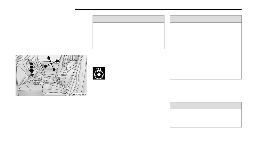
This feature allows you to tilt the steering column 

upward or downward. It also allows you to lengthen 

or shorten the steering column. The tilt/

telescoping lever is located below the steering 

wheel at the end of the steering column.

Tilt/Telescoping Lever

To unlock the steering column, push the tilt/

telescoping lever downward (toward the floor). To 

tilt the steering column, move the steering wheel 

upward or downward as desired. To lengthen or 

shorten the steering column, pull the steering 

wheel outward or push it inward as desired.
To lock the steering column in position, pull the tilt/

telescoping lever upward until fully engaged.

H

EATED

 S

TEERING

 W

HEEL

 — 


I

F

 E

QUIPPED


The steering wheel contains a heating 

element that helps warm your hands in 

cold weather. The heated steering wheel 

has only one temperature setting. Once 

the heated steering wheel switch has been turned 

on, it will stay on for an average of 80


minutes or 

more before automatically shutting off. This time 

will vary based on environmental temperatures. 

The heated steering wheel can shut off early or 

may not turn on when the steering wheel is already 

warm. The heated steering wheel control button is 

located in your vehicle’s touchscreen or on the 

instrument panel.
For information on use with the Remote Start 

system, see  

Ú


page


19.

SEATS    

Seats are a part of the Occupant Restraint system 

of the vehicle.

WARNING!


Do not adjust the steering column while driving. 

Adjusting the steering column while driving or 

driving with the steering column unlocked, could 

cause the driver to lose control of the vehicle. 

Failure to follow this warning may result in 

serious injury or death.

WARNING!


Persons who are unable to feel pain to the 

skin because of advanced age, chronic illness, 

diabetes, spinal cord injury, medication, 

alcohol use, exhaustion, or other physical 

conditions must exercise care when using the 

steering wheel heater. It may cause burns 

even at low temperatures, especially if used 

for long periods.

Do not place anything on the steering wheel 

that insulates against heat, such as a blanket 

or steering wheel covers of any type and mate

-

rial. This may cause the steering wheel heater 

to overheat.

WARNING!


It is dangerous to ride in a cargo area, inside 

or outside of a vehicle. In a collision, people 

riding in these areas are more likely to be seri

-

ously injured or killed.


GETTING TO KNOW YOUR VEHICLE


27

M

ANUAL

 F

RONT

 S

EATS

Manual Front Seats Forward/Rearward 

Adjustment 

On models equipped with manual seats, the 

adjusting bar is located at the front of the seats, 

near the floor.

Manual Seat Adjustment Levers

While sitting in the seat, lift up on the bar and move 

the seat forward or rearward. Release the bar once 

you have reached the desired position. Then, using 

body pressure, move forward and rearward on the 

seat to be sure that the seat adjusters have 

latched.

Height Adjustment

The driver’s seat height can be raised or lowered 

by using a lever, located on the outboard side of 

the seat. Pull upward on the lever to raise the seat 

height or push downward on the lever to lower the 

seat height.

Manual Recline Adjustment

To adjust the seatback, lift the lever located on the 

outboard side of the seat, lean back to the desired 

position and release the lever. To return the 

seatback, lift the lever, lean forward and release 

the lever.

M

ANUAL

 R

EAR

 S

EAT

 A

DJUSTMENT

Do not allow people to ride in any area of your 

vehicle that is not equipped with seats and 

seat belts. In a collision, people riding in these 

areas are more likely to be seriously injured or 

killed.

Be sure everyone in your vehicle is in a seat 

and using a seat belt properly.

WARNING!


Adjusting a seat while the vehicle is moving is 

dangerous. The sudden movement of the seat 

could cause you to lose control. The seat belt 

might not be adjusted properly and you could 

be injured. Adjust the seat only while the 

vehicle is parked.

Do not ride with the seatback reclined so that 

the shoulder belt is no longer resting against 

your chest. In a collision you could slide under 

the seat belt and be seriously or even fatally 

injured. Use the recliner only when the vehicle 

is parked.

WARNING!

1 — Forward/Rearward Adjustment Bar
2 — Seat Height Adjustment Lever (If Equipped)
3 — Recline Lever

WARNING!


Do not pile luggage or cargo higher than the top 

of the seatback. This could impair visibility or 

become a dangerous projectile in a sudden stop 

or collision.

2

28


GETTING TO KNOW YOUR VEHICLE


Split Rear Seats

The split rear seat has the ability to fold flat which 

increases the storage of the rear cargo area.
NOTE:

Prior to folding the rear seat down, it may be 

necessary to position the front seat to its 

mid-track position. Be sure that the front seats 

are fully upright and positioned forward, this will 

allow the rear seat to fold down easily.

Prior to folding the rear seat, you must secure 

the rear armrest in the upright position.

You may experience deformation in the seat 

cushion from the seat belt buckles if the seats 

are left folded for an extended period of time. 

This is normal and by simply unfolding the seats 

to the open position, over time the seat cushion 

will return to its normal shape.

Cargo Area Enlargement

Folding both sides of the rear seat provides 

additional storage in the rear cargo area.
Proceed as follows:
1. Fully lower the rear seat head restraints.
2. Move the seat belts to the outboard side of the 

seat.

3. Pull the seatback release lever to fold both 

sides of the rear seatbacks completely 

forward.

Partial Enlargement Of The Cargo Area

Enlargement of the left side of the cargo area 

allows you to carry a single passenger on the right 

side of the rear seat, while the enlargement of the 

right side allows you to carry two passengers.
Proceed as follows:
1. Remove the rear shelf (if equipped)  

Ú


page


58.

2. Fully lower the rear seat head restraints.
3. Move the seat belts to the outboard side of the 

seat and rest them on the seat belt guide.

4. Pull the seatback release lever to fold the left 

or right rear seatback completely forward.

Rear Seat Release

Seatback Repositioning

NOTE:


If interference from the cargo area prevents the 

seatback from fully locking, you will have difficulty 

returning the seat to its proper position.
1. Move the seat belts to the seat belt guides on 

the top edge of the seat to ensure the 

seatbacks properly latch.

2. Lift the seatbacks, pushing them back until 

they lock on both the latches. Verify the red 

notches are no longer visible on the release 

lever. If the red notches are visible, the 

seatback is not secure.

WARNING!


It is extremely dangerous to ride in a cargo 

area, inside or outside of a vehicle. In a colli

-

sion, people riding in these areas are more 

likely to be seriously injured or killed.

Do not allow people to ride in any area of your 

vehicle that is not equipped with seats and 

seat belts.

Be sure everyone in your vehicle is in a seat 

and using a seat belt properly.

1 — Seat Belt Guide
2 — Seatback Release Lever


GETTING TO KNOW YOUR VEHICLE


29

P

OWER

 A

DJUSTMENT

 (F

RONT

) — 


I

F

 E

QUIPPED

Power Seat Switch

Some models may be equipped with a power 

driver's seat and/or power passenger seat. The 

power seat switch and power seat recliner switch 

are located on the outboard side of the seat near 

the floor. Use the power seat switch to adjust seat 

height, angle, or forward/rearward position. Use 

the power seat recline switch to adjust the angle of 

the seatback.
Forward Or Rearward Adjustment
The seat can be adjusted both forward and 

rearward. Push the seat switch forward or 

rearward, the seat will move in the direction of the 

switch. Release the switch when the desired 

position has been reached.

Height Adjustment
The height of the seats can be adjusted up or 

down. Pull upward or push downward on the seat 

switch, the seat will move in the direction of the 

switch. Release the switch when the desired 

position is reached.
Tilt Adjustment
The angle of the seat cushion can be adjusted up 

or down. Pull upward or push downward on the 

front of the seat switch and the front of the seat 

cushion will move in the direction of the switch.

Reclining The Seatback 

The seatback can be reclined both forward and 

rearward. Push the seat recliner switch forward or 

rearward. The seatback will move in the direction 

of the switch. Release the switch when the desired 

position has been reached.

Power Seat Recliner Switch

WARNING!


Adjusting a seat while driving may be 

dangerous. Moving a seat while driving could 

result in loss of control which could cause a 

collision and serious injury or death.

Seats should be adjusted before fastening the 

seat belts and while the vehicle is parked. 

Serious injury or death could result from a 

poorly adjusted seat belt.

Do not ride with the seatback reclined so that 

the shoulder belt is no longer resting against 

your chest. In a collision you could slide under 

the seat belt, which could result in serious 

injury or death.

CAUTION!


Do not place any article under a power seat or 

impede its ability to move as it may cause 

damage to the seat controls. Seat travel may 

become limited if movement is stopped by an 

obstruction in the seat’s path.

2

30


GETTING TO KNOW YOUR VEHICLE


Power Lumbar Adjustment— If Equipped

Push the switch forward or rearward to increase or 

decrease the lumbar support. Push the switch 

upward or downward to raise or lower the lumbar 

support.

Power Lumbar Switch

NOTE:


Power seat adjustments are only allowed when the 

ignition is in the ON position, and for about 

30


minutes after it is placed in the OFF position.

H

EATED

 S

EATS

 — I

F

 E

QUIPPED


The heated seat buttons are located in 

your vehicle’s touchscreen or on the 

instrument panel.

You can choose between two heating levels:

Press the heated seat button once to turn the HI 

setting on.

Press the heated seat button a second time to 

turn the LO setting on.

Press the heated seat button a third time to turn 

the heating elements off.

If the operator presses the heated seat button a 

second time to turn on the LO setting, the display 

will change from HI to LO, and the LO level setting 

will turn off automatically after 45


minutes.

If the HI-level setting is selected, the system will 

automatically switch to LO-level after 

approximately 145


minutes of continuous 

operation. At that time, the display will change 

from HI to LO, indicating the change. The LO-level 

setting will turn off automatically after 

approximately 60


minutes.

NOTE:


The engine must be running for the heated seats to 

operate. 
The timing values may vary the heated seat 

settings depending on the outside ambient 

temperature.
For information on use with the Remote Start 

system, see  

Ú


page


19.

WARNING!


Persons who are unable to feel pain to the 

skin because of advanced age, chronic illness, 

diabetes, spinal cord injury, medication, 

alcohol use, exhaustion or other physical 

condition must exercise care when using the 

seat heater. It may cause burns even at low 

temperatures, especially if used for long 

periods of time.

Do not place anything on the seat or seatback 

that insulates against heat, such as a blanket 

or cushion. This may cause the seat heater to 

overheat. Sitting in a seat that has been over

-

heated could cause serious burns due to the 

increased surface temperature of the seat.


GETTING TO KNOW YOUR VEHICLE


31

U

NFOLDING

 T

HE

 R

EAR

 A

RMREST


40/20/40

Pull the rear armrest tab to release it from the seat 

and pull forward.

Armrest Tab Location

Fold Center Armrest Forward

The center part of the rear seat can also be used 

as a rear armrest with cupholders.

Rear Armrest With Cupholders

H

EAD

 R

ESTRAINTS


Head restraints are designed to reduce the risk of 

injury by restricting head movement in the event of 

a rear impact. Head restraints should be adjusted 

so that the top of the head restraint is located 

above the top of your ear.

WARNING!


Be certain that the seatback is securely locked 

into position. If the seatback is not securely 

locked into position the seat will not provide the 

proper stability for child seats and/or 

passengers. An improperly latched seat could 

cause serious injury.

WARNING!


All occupants, including the driver, should not 

operate a vehicle or sit in a vehicle’s seat until 

the head restraints are placed in their proper 

positions in order to minimize the risk of neck 

injury in the event of a crash.

Head restraints should never be adjusted 

while the vehicle is in motion. Driving a vehicle 

with the head restraints improperly adjusted 

or removed could cause serious injury or 

death in the event of a collision.

2

32


GETTING TO KNOW YOUR VEHICLE


Front Head Restraints

Your vehicle is equipped with front driver and 

passenger head restraints.
To raise the head restraint, pull upward on the 

head restraint. To lower the head restraint, push 

the adjustment button, located at the base of the 

head restraint, and push downward on the head 

restraint.

Head Restraint Adjustment Button

NOTE:


The head restraints should only be removed by 

qualified technicians, for service purposes only. If 

either of the head restraints require removal, see 

an authorized dealer.

Rear Head Restraints

Your vehicle is equipped with two outboard head 

restraints and one center head restraint for its rear 

passengers. The rear head restraints can be raised 

or lowered. When the center seat is being 

occupied, the head restraint should be in the 

raised position. When there are no occupants in 

the center seat, the head restraint can be lowered 

for maximum visibility for the driver.

To raise the head restraint, pull upward on the 

head restraint.
To lower the head restraint, push the adjustment 

button, located at the base of the head restraint, 

and push downward on the head restraint.

Adjustment Buttons

NOTE:


The head restraints should only be removed by 

qualified technicians, for service purposes only. If 

either of the head restraints require removal, see 

an authorized dealer.

WARNING!


All occupants, including the driver, should not 

operate a vehicle or sit in a vehicle’s seat until 

the head restraints are placed in their proper 

positions in order to minimize the risk of neck 

injury in the event of a crash.

Head restraints should never be adjusted 

while the vehicle is in motion. Driving a vehicle 

with the head restraints improperly adjusted 

or removed could cause serious injury or 

death in the event of a collision.


GETTING TO KNOW YOUR VEHICLE


33

UCONNECT VOICE RECOGNITION 

I

NTRODUCING

 V

OICE

 R

ECOGNITION

Start using Uconnect Voice Recognition with these 

helpful quick tips. It provides the key Voice 

Commands and tips you need to know to control 

your vehicle’s Voice Recognition (VR) system.

Uconnect 4C NAV

If you see the NAV icon on the bottom bar or in the 

Apps menu of your 8.4-inch touchscreen, you have 

the Uconnect 4C NAV system. If not, you have a 

Uconnect 4C with 8.4-inch display system.

B

ASIC

 V

OICE

 C

OMMANDS

The following basic Voice Commands can be given 

at any point while using your Uconnect system.
Push the VR button  . After the beep, say:

“Cancel” to stop a current voice session.

“Help” to hear a list of suggested Voice 

Commands.

“Repeat” to listen to the system prompts again.

Notice the visual cues that inform you of your Voice 

Recognition system’s status.

G

ET

 S

TARTED

The   VR button is used to activate/deactivate 

your Voice Recognition system.
Helpful hints for using Voice Recognition:

Reduce background noise. Wind noise and 

passenger conversations are examples of noise 

that may impact recognition.

Speak clearly at a normal pace and volume 

while facing straight ahead.

Each time you give a Voice Command, first push 

the VR button, wait until after the beep, then say 

your Voice Command.

You can interrupt the help message or system 

prompts by pushing the VR button and saying a 

Voice Command from the current category.

Uconnect Voice Command Buttons

A

DDITIONAL

 I

NFORMATION

Uconnect are registered trademarks and Mopar 

Owner Connect is a trademark of FCA US LLC. 

SiriusXM® and all related marks and logos are 

trademarks of SiriusXM® Radio Inc  

Ú


page


349.

For Uconnect system support, call 

1-877-855-8400 (24 hours a day 7 days a week) 

or visit DriveUconnect.com (US) or 

DriveUconnect.ca (Canada).

1 — Push To Start Or Answer A Phone Call and 

Send Or Receive A Text
2 — Push The Voice Recognition Button To Begin 

Radio, Media, Navigation And Climate Functions

2

34


GETTING TO KNOW YOUR VEHICLE


MIRRORS

I

NSIDE

 R

EARVIEW

 M

IRROR

Manual Mirror — If Equipped

The rearview mirror can be adjusted up, down, left, 

and right. The mirror should be adjusted to center 

on the view through the rear window. Headlight 

glare from vehicles behind you can be reduced by 

moving the lever under the mirror to the night 

position (toward the rear of the vehicle). The mirror 

should be adjusted while the lever under the mirror 

is set in the day position (toward the windshield).

Mirror Adjustment

NOTE:


The mirror will automatically release in the event of 

heavy contact with a passenger.

Auto Dimming Mirror — If Equipped

This mirror automatically adjusts for headlight 

glare from vehicles behind you. You can turn the 

feature on or off by pushing the button at the base 

of the mirror. A light to the left of the button will 

illuminate to indicate when the dimming feature is 

activated. The sensor to the right of the button 

does not illuminate.

Dimming Mirror

NOTE:


This feature is disabled when the vehicle’s trans

-

mission has been placed in REVERSE.

I

LLUMINATED

 V

ANITY

 M

IRRORS

 — 


I

F

 E

QUIPPED


To access an illuminated vanity mirror, flip down 

one of the visors and lift the mirror cover.

Lift Cover For Mirror


GETTING TO KNOW YOUR VEHICLE


35

Sun Visor “Slide-On-Rod” Feature — 


If Equipped

To extend the sun visor, proceed as follows:
1. Place the sun visor against the door glass by 

detaching it from the hook and turning it 

toward the side window.

2. Slide the visor along the rod to provide 

coverage more to the rear.

Sliding Sun Visor

3. Slide out the sun visor extender for even more 

side coverage toward the rear.

Using The Extender

O

UTSIDE

 M

IRRORS


Power Adjustment Mirrors — If Equipped

The power mirror switch is located on the driver’s 

door panel.
To adjust the mirror, rotate the mirror selection 

switch to the left or to the right and then push the 

mirror adjustment switch in the four directions 

indicated by arrows.

NOTE:

To adjust the power mirrors, the ignition must be 

in the ON/RUN position.

The power mirror switches will remain active for 

up to three minutes after the ignition is placed 

in the OFF position. Opening either front door 

will cancel this feature.

Once the mirror is adjusted, rotate the control to 

the neutral position to avoid accidental move

-

ments.

Power Mirror Switch

1 — Mirror Selector Switch
2 — Mirror Adjustment Switch
3 — Power Folding Mirror Switch

2

36


GETTING TO KNOW YOUR VEHICLE


Manual Adjustment Mirrors — If Equipped

To adjust the exterior mirrors, push the corners of 

the mirrors until the desired alignment is obtained.

Manual Adjustment Mirror

Folding Mirror

The exterior mirrors are hinged to allow the mirror 

to pivot forward or rearward to help avoid damage. 

The mirror has three detent positions: full forward, 

normal and full rearward.

Folding Exterior Mirror

Power Folding/Unfolding Mirrors — If Equipped
Push the mirror fold/unfold switch briefly to fold or 

unfold the exterior mirrors.
To fold or unfold the exterior mirrors, the ignition 

must be in the ON/RUN position.
NOTE:


The fold/unfold mirrors switch will remain active 

for up to three minutes after the ignition is placed 

in the OFF position. Opening either front door will 

cancel this feature.

H

EATED

 M

IRRORS

 — I

F

 E

QUIPPED


These mirrors are heated to melt frost or 

ice. This feature can be activated 

whenever you turn on the Rear Window 

Defroster  

Ú


page


44.

EXTERIOR LIGHTS

H

EADLIGHT

 S

WITCH


The headlight switch is located on the left side of 

the instrument panel. The headlight switch 

controls the operation of the headlights, side 

marker and parking lights, daytime running lights, 

fog lights and the dimming of the instrument 

cluster and interior lighting.

Headlight Switch

1 — Rotate Headlight Control
2 — Ambient Lighting Control
3 — Instrument Panel Dimmer Control
4 — Front Fog Light Switch


GETTING TO KNOW YOUR VEHICLE


37

Turning on the headlights will illuminate the 

instrument cluster and the controls located on the 

instrument panel.
NOTE:


On vehicles sold in Canada, both the rear position 

lights and Daytime Running Lights (DRLs) will turn 

on when the headlight switch is rotated to the O 

(off) position.

D

AYTIME

 R

UNNING

 L

IGHTS

 (DRL

S

) —


I

F

 E

QUIPPED


The Daytime Running Lights (DRLs), if enabled 

through Uconnect Settings, will turn on when the 

instrument cluster is on and remain on unless the 

headlights are turned on or the instrument cluster 

is switched off.
NOTE:

For vehicles sold in Canada, the Daytime 

Running Lights will automatically deactivate 

when the front fog lights are turned on.

On some vehicles, the Daytime Running Lights 

may deactivate, or reduce intensity, on one side 

of the vehicle (when a turn signal is activated on 

that side), or on both sides of the vehicle (when 

the hazard warning lights are activated).

H

IGH

 B

EAMS


To activate the high beam headlights, push the 

multifunction lever forward (toward the front of the 

vehicle), and an indicator will illuminate in the 

instrument cluster display.
To deactivate the high beam headlights, pull the 

multifunction lever rearward (toward the rear of 

the vehicle).

High Beam And Turn Signal Controls

NOTE:


The headlights must be on for the high beams to 

activate.

A

UTOMATIC

 H

IGH

 B

EAM

 H

EADLAMP


C

ONTROL

 — I

F

 E

QUIPPED


The Automatic High Beam Headlamp Control 

system provides increased forward lighting at night 

by automatically controlling the high beams 

through the use of a camera mounted on the 

inside rearview mirror. This camera detects vehicle 

specific light and automatically switches from high 

beams to low beams until the approaching vehicle 

is out of view.
NOTE:

The multifunction lever must be in the high 

beam position in order to activate the Automatic 

High Beams.

The Automatic High Beam Headlamp Control 

can be turned on or off using the Uconnect 

system  

Ú


page


133.

Broken, muddy, or obstructed headlights and 

taillights of vehicles in the field of view will 

cause headlights to remain on longer (closer to 

the vehicle). Also, dirt, film, and other obstruc

-

tions on the windshield or camera lens will 

cause the system to function improperly.

When set to AUTO, the system automatically turns 

the headlights on or off based on ambient light 

levels.

F

LASH

-T

O

-P

ASS


You can signal another vehicle with your headlights 

by lightly pulling the multifunction lever toward you. 

This will cause the high beam headlights to turn on, 

and remain on, until the lever is released.

2

38


GETTING TO KNOW YOUR VEHICLE


A

UTOMATIC

 H

EADLIGHTS

 — I

F

 E

QUIPPED


This system automatically turns the headlights on 

or off according to ambient light levels. To turn the 

system on, rotate the headlight switch clockwise to 

the last detent (AUTO position) for automatic 

headlight operation. To turn the automatic system 

off, move the headlight switch out of the AUTO 

position.
NOTE:


The ignition must be in the ON/RUN or START 

position before the headlights will come on in the 

automatic mode.

Dusk Sensor

There is an infrared LED sensor that works with the 

rain sensor, located on the windshield. It detects 

changes in light intensity outside the vehicle, 

based on the sensitivity of light set by using the 

menu on the display or on the Uconnect system.
The higher the sensitivity, the lesser the amount of 

external light required for controlling the lighting.
To turn the dusk sensor on, rotate the headlight 

switch to the AUTO position. To turn it off, rotate the 

headlight switch to a position other than AUTO.
NOTE:


The dusk sensor can only be activated with the 

ignition in the ON/RUN position.

P

ARKING

 L

IGHTS

Rotate the headlight switch to the first detent to 

turn on the parking lights. The parking light 

indicator in the instrument cluster display will 

illuminate.

H

EADLIGHT

 T

IME

 D

ELAY


This feature provides the safety of headlight 

illumination for up to 90 seconds when leaving 

your vehicle in an unlit area.
The time delay of the headlights is programmable 

between 0, 30, 60 and 90 seconds within 

Uconnect Settings  

Ú


page


133.

Headlight Delay Activation
To activate the delay feature, place the ignition in 

the OFF position while the headlights are still on. 

The delay interval begins when the headlight 

switch is turned off from the low beam position.
If the headlight switch is in AUTO and the 

headlights were on before the ignition was turned 

off, the delay interval begins automatically.
Headlight Delay Deactivation
The feature is disabled by turning on the 

headlights, the parking lights or by placing the 

ignition in the RUN position.
If you shut off the lights before the ignition is 

turned on, they will turn off in the normal manner.

NOTE:


The lights must be turned off within two minutes of 

placing the ignition in the OFF position to activate 

this feature.

F

RONT

 F

OG

 L

IGHTS

 — I

F

 E

QUIPPED


The front fog light switch is built into the headlight 

switch.

Fog Light Switch

To activate the front fog lights, turn on the parking 

lights or the low beam headlights and push the fog 

light button on the headlight switch. The front fog 

lights feature is latching, which means that every 

time that the button is pressed and the fog lights 

are activated, the vehicle memorizes the request 

and reactivates the front fog lights every time that 

the parking lights or low beams are active. To 

deactivate the feature, push the front fog button 


GETTING TO KNOW YOUR VEHICLE


39

again. The front fog lights are deactivated each 

time the parking or low beam lights are 

deactivated or the ignition is placed in the OFF 

position.
An indicator light in the instrument cluster 

illuminates when the fog lights are turned on.
NOTE:


The fog lights will operate with the low beam head

-

lights or parking lights on. Selecting the high beam 

headlights will turn off the fog lights.
Cornering Lights
The cornering lights are a feature to improve 

visibility at night while turning the vehicle. When 

activated, a light incorporated in the front fog light 

will illuminate on the side of the vehicle the 

steering wheel is rotated or the turn signal 

indicator is on. It can be activated through the 

Uconnect system  

Ú


page


133.

T

URN

 S

IGNALS


Move the multifunction lever up or down to 

activate the turn signals. The arrows on each side 

of the instrument cluster display flash to show 

proper operation.

L

ANE

 C

HANGE

 A

SSIST

Lightly push the multifunction lever up or down, 

without moving beyond the detent, and the turn 

signal will flash five times then automatically turn 

off.

C

OURTESY

 L

IGHTS

The courtesy lights feature allows you to activate 

the low beam, parking lights, and sidemarker lights 

for 25 seconds when the vehicle is unlocked 

(through the key fob or the Passive Entry door 

handles [if equipped]). The courtesy lights feature 

can be activated or deactivated through the 

Uconnect Settings. When a door is open with the 

feature active, the activation of the lights is 

extended for five seconds. The feature is disabled 

when the vehicle is locked or when the ignition is 

placed in the ON/RUN position.

INTERIOR LIGHTS 

F

RONT

 M

AP

/R

EADING

 L

IGHTS

The courtesy lights are mounted between the sun 

visors above the rearview mirror. The light switches 

are used to turn the lights on or off.

Driver’s Courtesy Lights

Courtesy Light Switches

To operate the courtesy lights, push either the 

driver or passenger light switch.

1— Left Switch
2— Right Switch

2

40


GETTING TO KNOW YOUR VEHICLE


NOTE:

Before exiting the vehicle, make sure that the 

interior lights are turned off. This will prevent the 

battery from discharging once the doors are 

closed.

If a light is left on, it will automatically be turned 

off after approximately 15


minutes after the 

ignition is in the OFF position.

D

IMMER

 C

ONTROLS


Rotate the ambient dimmer control upward or 

downward to increase or decrease the brightness 

of the ambient light located in the overhead 

console, door handle lights, lower instrument 

panel lights, door map pocket lights, and cubby bin 

lights.
With the parking lights or headlights on, rotate the 

instrument panel dimmer control upward or 

downward to increase or decrease the brightness 

of the instrument panel. The instrument panel 

dimmer has two positions at the top of the thumb 

wheel. The first top detent position puts the interior 

lighting into daytime mode and the very top detent 

position illuminates all the interior lights. The 

bottom detent position of the instrument panel 

dimmer dims the internal backlights to their lowest 

dimmable setting and disables the interior lights.

Dimmer Controls

R

EAR

 L

IGHTS

On vehicles equipped with a sunroof, there are two 

interior lights located above the grab handles of 

the rear doors. When the ignition is in the ON/RUN 

position, the lights come on when any door is 

opened.
Push the button on the light once to turn the light 

on manually, and push the button a second time to 

turn the light off.

Rear Light Button (If Equipped With Sunroof)

On vehicles not equipped with a sunroof, a single 

dome light is located in the center of the roof.

Rear Dome Light Buttons (Sunroof Not Equipped)

1 - Ambient Light Dimmer Control Switch
2 - Instrument Panel Dimmer Control Switch

1 — Dome Defeat Button
2 — Dome On Button


GETTING TO KNOW YOUR VEHICLE


41

To operate the rear dome light, proceed as follows:

Push the switch to the on/right position from its 

center position and the lights are always on.

Push the switch to the off/left position from its 

center position and the lights are always off.

Leave the switch in the center position, and the 

lights are turned on and off when the doors are 

opened or closed.

D

OME

 L

IGHT

 T

IMING

The dome light will automatically illuminate when 

the doors are unlocked, the doors are opened or 

after the doors are closed.
Timing Entering The Vehicle
The dome lights illuminate in the following ways:

When the doors are unlocked, the dome light 

will illuminate for approximately 27 seconds.

When one of the doors is opened, the dome light 

will illuminate for approximately three minutes.

When the doors are closed, the dome light will 

automatically shut off after approximately 27 

seconds.

The timing stops once the ignition is placed in the 

ON/RUN position.

The dome light will turn off under any of the 

following conditions:

The dome light is disabled when the ignition is 

placed in the ON/RUN position.

The dome lights will turn off automatically when 

the doors are locked.

The dome lights will automatically turn off after 

approximately 15


minutes of inactivity to 

preserve the battery.

Timing Exiting The Vehicle
The dome light will illuminate under the following 

conditions when the ignition is placed to the OFF 

position and the key is removed:

The dome light will illuminate for 27 seconds 

after the ignition is placed in the OFF position.

The opening of one of the doors (approximately 

three minutes).

After closing a door (approximately 27 seconds).

The dome light timing is disabled when the doors 

are locked.

WINDSHIELD WIPERS AND WASHERS 

The windshield wiper/washer controls are located 

on the windshield wiper/washer lever on the right 

side of the steering column. The front wipers are 

operated by rotating a switch, located on the end of 

the lever.

Windshield Wiper Lever

1 — Push Forward For Rear Washer
2 — Rotate For Rear Wiper Operation
3 — Rotate For Front Wiper Operation
4 — Pull For Front Washer
5 — Push Up For Mist

CAUTION!


Always remove any buildup of snow that 

prevents the windshield wiper blades from 

returning to the “park” position. If the windshield 

wiper switch is turned off, and the blades cannot 

return to the “park” position, damage to the 

wiper motor may occur.

2


Content      ..      1      2      3      ..