Jeep Gladiator (2022 year). Manual in english - page 4
 

  Index      Manuals     Jeep Gladiator (2022 year). Manual in english


Search            copyright infringement  


Content      ..     2      3      4      5     ..


Jeep Gladiator (2022 year). Manual in english - page 4


GETTING TO KNOW YOUR VEHICLE

59

If you have any problems, or require assistance, 

please call toll-free 1-800-355-3515 or, on the 

Internet at 

HomeLink.com

 for information or 

assistance.

EXTERIOR LIGHTS  

H

EADLIGHT

 S

WITCH

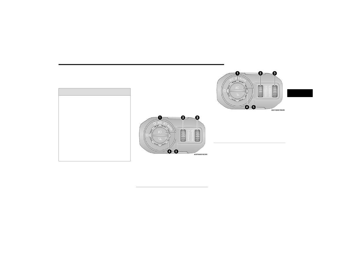
The headlight switch is located on the left side of 

the instrument panel. This switch controls the 

operation of the headlights, parking lights, 

automatic headlights (if equipped), instrument 

panel lights, instrument panel light dimming, 

interior lights, and fog lights (if equipped).

Headlight Switch

Headlight Switch (Vehicles Sold In Canada)

NOTE:

Vehicles sold in Canada are equipped with a head

-

light switch without the OFF position. In order to 

turn the exterior lights off, the headlight switch 

must be rotated to AUTO position.
Rotate the headlight switch clockwise to the first 

detent for parking lights and instrument panel light 

operation. Rotate the headlight switch to the 

second detent for headlights, parking lights, and 

instrument panel light operation.

WARNING!

Vehicle exhaust contains carbon monoxide, a 

dangerous gas. Do not run your vehicle in the 

garage while programming the transceiver. 

Exhaust gas can cause serious injury or death.

Your motorized door or gate will open and 

close while you are programming the universal 

transceiver. Do not program the transceiver if 

people, pets or other objects are in the path of 

the door or gate. Only use this transceiver with 

a garage door opener that has a “stop and 

reverse” feature as required by Federal safety 

standards. This includes most garage door 

opener models manufactured after 1982. Do 

not use a garage door opener without these 

safety features.

1 — Rotate Headlight Switch
2 — Ambient Light Dimmer Control
3 — Instrument Panel Dimmer Control
4 — Push Bed Light
5 — Push Front Fog Light

1 — Rotate Headlight Switch
2 — Ambient Light Dimmer Control
3 — Instrument Panel Dimmer Control
4 — Push Bed Light
5 — Push Front Fog Light

2

60

GETTING TO KNOW YOUR VEHICLE


NOTE:

For vehicles sold in Canada, rotate the headlight 

switch clockwise from the parking lights and 

instrument panel light position to the first detent to 

turn on headlights, parking lights, and instrument 

panel light. Rotate the headlight switch to the 

second detent for the AUTO position.

D

AYTIME

 R

UNNING

 L

IGHTS

(DRL

S

) — I

F

 E

QUIPPED


The Daytime Running Lights (DRLs) are in a 

dedicated position below the headlight assembly. 

DRLs are active when the low beams are not on 

while the vehicle’s transmission is in any position 

(automatic transmission), or when the vehicle 

begins to move (manual transmission).

NOTE:

For vehicles sold in Canada, the DRLs will auto

-

matically deactivate when the front fog lights 

are turned on.

On some vehicles, the Daytime Running Lights 

may deactivate, or reduce intensity, on one side 

of the vehicle (when a turn signal is activated on 

that side), or on both sides of the vehicle (when 

the hazard warning lights are activated).

H

IGH

/L

OW

 B

EAM

 S

WITCH


The High/Low Beam switch is located within the 

multifunction lever on the left side of the steering 

wheel. High beam headlights can be used for 

improved visibility in low lit areas when there is no 

oncoming traffic. Otherwise, it is recommended to 

use the low beam headlights to reduce glare to 

other vehicles.
With the headlight switch activated, push the 

multifunction lever toward the instrument panel to 

switch the headlights to high beams. The lever will 

return to the centered position. To return the 

headlights to low beam, pull the lever toward the 

steering wheel, or push the lever toward the 

instrument panel.

Multifunction Lever

A

UTOMATIC

 H

IGH

 B

EAM

 H

EADLAMP


C

ONTROL

 — I

F

 E

QUIPPED


The Automatic High Beam Headlamp Control 

system provides increased forward lighting at night 

by automatically controlling the high beams 

through the use of a camera mounted on the 

vehicle’s header. This camera detects vehicle 

specific light and automatically switches from high 

beams to low beams until the approaching vehicle 

is out of view.

NOTE:

The Automatic High Beam Headlamp Control 

can be turned on or off by selecting “ON” under 

“Auto Dim High Beams” within your Uconnect 

Settings  

Ú

page 228, as well as turning the 

headlight switch to the AUTO position and 

placing the multifunction lever in the high beam 

position.

Broken, muddy, or obstructed headlights and 

taillights of vehicles in the field of view will 

cause headlights to remain on longer (closer to 

the vehicle). Also, dirt, film, and other obstruc

-

tions on the windshield or camera lens will 

cause the system to function improperly.

GETTING TO KNOW YOUR VEHICLE

61

F

LASH

-T

O

-P

ASS


The Flash-To-Pass feature will illuminate the high 

beam headlights temporarily to signal another 

vehicle of a passing occurrence. Pull and hold the 

Multifunction Lever to activate the Flash-To-Pass 

feature. When the lever is released, the 

Flash-To-Pass feature will deactivate.

A

UTOMATIC

 H

EADLIGHTS

 — I

F

 E

QUIPPED


The Automatic Headlight System will turn the 

headlights on or off according to ambient light 

levels. To turn the system on, rotate the headlight 

switch clockwise to the last detent for automatic 

headlight operation. When the system is on, the 

headlight time delay feature is also on. This means 

the headlights will stay on for up to 90 seconds 

(programmable through the Uconnect Settings  

Ú

page 228) after you place the ignition into the 

OFF position. To turn the automatic system off, 

move the headlight switch out of the AUTO 

position.

NOTE:

The engine must be running before the headlights 

will come on in the automatic mode.

L

IGHTS

-O

N

 R

EMINDER

If the headlights or parking lights are left on after 

the ignition is placed in the OFF position, the 

vehicle will chime when the driver’s door is 

opened.

F

RONT

 F

OG

 L

IGHTS

 — I

F

 E

QUIPPED


The Front Fog Lights are located on the front of the 

vehicle below the headlights. When activated, 

these lights add illumination directed at the driving 

surface to aid in poor visibility conditions.
To activate the Front Fog Lights, turn on the 

parking lights or low beam headlights and push the 

fog light switch. Pushing the fog light switch a 

second time will turn the front fog lights off.

Front Fog Light Switch

Front Fog Light Switch (Vehicles Sold In Canada)

T

URN

 S

IGNALS

Move the multifunction lever up or down to 

activate the turn signals. The arrows on each side 

of the instrument cluster flash to show proper 

operation.

NOTE:

If either light remains on and does not flash, or 

there is a very fast flash rate, check for a defective 

outside light bulb.

L

ANE

 C

HANGE

 A

SSIST

 — I

F

 E

QUIPPED

Lightly push the multifunction lever up or down, 

without moving beyond the detent, and the turn 

signal will flash three times then automatically turn 

off.

2

62

GETTING TO KNOW YOUR VEHICLE


B

ED

 L

IGHTS

 — I

F

 E

QUIPPED


The bed lights will illuminate the bed and cargo 

area. Bed lights are turned on by pushing the bed 

light switch located on the lower half of the 

headlight switch.

Bed Light Switch

Bed Light Switch (Vehicles Sold In Canada)

A telltale will illuminate in the instrument cluster 

display when these lights are on. Pushing the 

switch a second time will turn the lights off.
The bed lights will turn on for approximately 60 

seconds when a key fob unlock button is pushed, 

as part of the Illuminated Entry feature.

INTERIOR LIGHTS 

I

NTERIOR

 C

OURTESY

 L

IGHTS

The Interior Courtesy Lights will turn on when the 

front doors are opened, by rotating the instrument 

panel dimmer control (dial on the right) on the 

headlight switch fully upward while the doors are 

closed, or if equipped, when the unlock button is 

pushed on the key fob.
The Interior Courtesy Lights are located in the 

center of the vehicle’s sport bar, and consist of one 

large center light and four smaller reading lights. 

Each reading light can be turned on by pushing the 

lens. Pushing the lens a second time will turn the 

light off.

Interior Courtesy Lights

When a door is open and the interior lights are on, 

rotating the instrument panel dimmer control to 

the extreme bottom position will cause all the 

interior lights to turn off. This allows the doors to 

stay open for extended periods of time without 

discharging the vehicle’s battery.

GETTING TO KNOW YOUR VEHICLE

63

D

IMMER

 C

ONTROLS

The dimmer controls are part of the headlight 

switch and are located on the left side of the 

instrument panel.

Dimmer Controls

Dimmer Controls (Vehicles Sold In Canada)

With the parking lights or headlights on, rotating 

the right dimmer control upward will increase the 

brightness of the instrument panel lights. Rotating 

the left dimmer control will adjust the ambient light 

levels below the instrument panel, near the floor.

WINDSHIELD WIPERS AND WASHERS  

The windshield wiper/washer control lever is 

located on the right side of the steering column; it 

operates the multiple wiper options. The front 

wipers are operated by rotating a switch, located at 

the end of the lever.

W

INDSHIELD

 W

IPER

 O

PERATION

Windshield Wiper/Washer Operation

Rotate the end of the lever upward to the first 

detent past the intermittent settings for low-speed 

wiper operation. Rotate the end of the lever 

upward to the second detent past the intermittent 

settings for high-speed wiper operation.

Intermittent Wipers
Use the intermittent wiper when weather 

conditions make a single wiping cycle, with a 

variable pause between cycles, desirable. Rotate 

the end of the lever to the first detent position for 

one of four intermittent settings. The delay cycle 

can be set anywhere between 1 to 18 seconds.

NOTE:

The wiper delay times depend on vehicle speed. If 

the vehicle is moving less than 10 mph (16 km/h), 

delay times will be doubled.

1 — Pull For Windshield Washer
2 — Rotate For Wiper Operation
3 — Push Up For Mist

CAUTION!

In cold weather, always turn off the wiper switch 

and allow the wipers to return to the park 

position before turning off the engine. If the 

wiper switch is left on and the wipers freeze to 

the windshield, damage to the wiper motor may 

occur when the vehicle is restarted.

2

64

GETTING TO KNOW YOUR VEHICLE


Windshield Washers
To use the washer, pull the lever toward you and 

hold until desired spray is reached. If the lever is 

pulled while in the delay range, the wiper will start 

and continue to operate for two or three wipe 

cycles after the lever is released. Then, the 

intermittent interval previously selected will 

resume.
If the lever is pulled while in the off position, the 

wipers will operate for two or three wipe cycles. 

Then, the wipers will turn off.

NOTE:

As a protective measure, the washer will stop if the 

switch is held for more than 20 seconds. Once the 

switch is released the washer will resume normal 

operation.

Mist
Push upward on the wiper lever to activate a single 

wipe to clear off-road mist or spray from a passing 

vehicle. As long as the lever is held up, the wipers 

will continue to operate.

NOTE:

The mist feature does not activate the washer 

pump; therefore, no washer fluid will be sprayed on 

the windshield. The wash function must be used in 

order to spray the windshield with washer fluid.
For information on wiper care and replacement, 

see  

Ú

page 405.

CLIMATE CONTROLS

The Climate Control system allows you to regulate 

the temperature, air flow, and direction of air 

circulating throughout the vehicle. The controls are 

located on the touchscreen (if equipped) and on 

the instrument panel below the radio.

A

UTOMATIC

 C

LIMATE

 C

ONTROL


D

ESCRIPTIONS

 A

ND

 F

UNCTIONS

Uconnect 4 With 7-inch Display Automatic 

Climate Controls

Uconnect 4C/4C NAV With 8.4-inch Display Automatic 

Climate Controls

WARNING!

Sudden loss of visibility through the windshield 

could lead to a collision. You might not see other 

vehicles or other obstacles. To avoid sudden 

icing of the windshield during freezing weather, 

warm the windshield with the defroster before 

and during windshield washer use.

GETTING TO KNOW YOUR VEHICLE

65

MAX A/C Button

Press and release the MAX A/C button on 

the touchscreen to change the current 

setting to the coldest output of air. MAX 

A/C sets the control for maximum cooling 

performance. The MAX A/C indicator illuminates 

when MAX A/C is on. Performing this function 

again will cause the MAX A/C operation to switch 

into manual mode and the MAX A/C indicator will 

turn off.

NOTE:

The MAX A/C button is only available on the touch

-

screen.

A/C Button

Press and release this button on the 

touchscreen, or push the button on the 

faceplate to change the current setting. 

The A/C indicator illuminates when A/C is 

ON.

The Air Conditioning (A/C) button allows the 

operator to manually activate or deactivate the air 

conditioning system. When the air conditioning 

system is turned on, cool dehumidified air will flow 

through the outlets into the cabin.

NOTE:

If fog or mist appears on the windshield or side 

glass, select Defrost mode, and increase blower 

speed if needed.

If your air conditioning performance seems 

lower than expected, check the front of the A/C 

condenser (located in front of the radiator), for 

an accumulation of dirt or insects. Clean with a 

gentle water spray from the front of the radiator 

and through the condenser.

Recirculation Button

Press and release this button on the 

touchscreen, or push the button on the 

faceplate to change the system between 

recirculation mode and outside air mode. 

The Recirculation indicator and the A/C indicator 

illuminate when the Recirculation button is 

pressed. Recirculation can be used when outside 

conditions such as smoke, odors, dust, or high 

humidity are present. Recirculation can be used in 

all modes. Recirculation may be unavailable 

(button on the touchscreen greyed out) if 

conditions exist that could create fogging on the 

inside of the windshield. The A/C can be 

deselected manually without disturbing the mode 

control selection. Continuous use of the 

Recirculation mode may make the inside air stuffy 

and window fogging may occur. Extended use of 

this mode is not recommended. Recirculation 

mode may automatically adjust to optimize 

customer experience for warming, cooling, 

dehumidification, etc.

AUTO Button

Press and release this button on the 

touchscreen, or push the button on the 

faceplate, to change the current setting. 

The AUTO indicator illuminates when 

AUTO is on. This feature automatically controls the 

interior cabin temperature by adjusting distribution 

and blower speed. Air conditioning (A/C) may be 

active during AUTO operation to improve 

performance. AUTO Mode is highly recommended 

for efficiency. Toggling this function will cause the 

system to switch between manual mode and 

automatic mode  

Ú

page 69.

Front Defrost

Turn the Mode control knob to Front 

Defrost to change the current airflow 

setting to Defrost mode. The Front 

Defrost indicator illuminates when Front 

Defrost is on. Air comes from the windshield and 

side window demist outlets. When the defrost 

button is selected, the blower level may increase. 

Use Defrost mode with maximum temperature 

settings for best windshield and side window 

defrosting and defogging. When toggling the front 

defrost mode button, the Climate Control system 

will return to the previous setting.

2

66

GETTING TO KNOW YOUR VEHICLE


Rear Defrost Button

Press and release the Rear Defrost 

Control button on the touchscreen, or 

push and release the button on the 

faceplate to turn on the rear window 

defroster and the heated outside mirrors (if 

equipped). The Rear Defrost indicator illuminates 

when the rear window defroster is on. The rear 

window defroster automatically turns off after 

10 minutes.

Driver And Passenger Temperature Up And 

Down Buttons

These buttons provide the driver and passenger 

with independent temperature control.

Push the red button on the faceplate or 

touchscreen or press and slide the 

temperature bar towards the red arrow 

button on the touchscreen for warmer 

temperature settings.

Push the blue button on the faceplate or 

touchscreen or press and slide the 

temperature bar towards the blue arrow 

button on the touchscreen for cooler 

temperature settings.

SYNC Button

Press the SYNC button on the 

touchscreen to toggle the Sync feature 

on/off. The SYNC indicator illuminates 

when SYNC is on. SYNC is used to 

synchronize the passenger temperature setting 

with the driver temperature setting. Changing the 

passenger temperature setting while in SYNC will 

automatically exit this feature.

NOTE:

The SYNC button is only available on the touch

-

screen.

Blower Control

Blower Control regulates the amount of 

air forced through the Climate Control 

system. There are seven blower speeds 

available. Adjusting the blower will cause 

automatic mode to switch to manual operation. 

The speeds can be selected using either the 

blower control knob on the faceplate or the 

buttons on the touchscreen.
Faceplate
The blower speed increases as you turn the blower 

control knob clockwise from the lowest blower 

setting. The blower speed decreases as you turn 

the blower control knob counterclockwise.
Touchscreen
Use the small blower icon to reduce the blower 

setting and the large blower icon to increase the 

blower setting. Blower can also be selected by 

pressing the blower bar area between the icons.

Mode Control

Turn the mode control knob or press one 

of the Mode buttons on the touchscreen 

to adjust airflow distribution. The airflow 

distribution mode can be adjusted so air 

comes from the instrument panel outlets, floor 

outlets, defrost outlets and demist outlets.

CAUTION!

Failure to follow these cautions can cause 

damage to the heating elements:

Use care when washing the inside of the rear 

window. Do not use abrasive window cleaners 

on the interior surface of the window. Use a 

soft cloth and a mild washing solution, wiping 

parallel to the heating elements. Labels can 

be peeled off after soaking with warm water.

Do not use scrapers, sharp instruments, or 

abrasive window cleaners on the interior 

surface of the window.

Keep all objects a safe distance from the 

window.

GETTING TO KNOW YOUR VEHICLE

67

Panel Mode

Air comes from the outlets in the 

instrument panel. Each of these outlets 

can be individually adjusted to direct the 

flow of air. The air vanes of the center 

outlets and outboard outlets can be moved up and 

down or side to side to regulate airflow direction. 

There is a shut-off wheel located below the air 

vanes to shut off or adjust the amount of airflow 

from these outlets.

Bi-Level Mode

Air comes from the instrument panel 

outlets and floor outlets. A slight amount 

of air is directed through the defrost and 

side window demister outlets.

NOTE:

Bi-Level mode is designed under comfort condi

-

tions to provide cooler air out of the panel outlets 

and warmer air from the floor outlets.

Floor Mode

Air comes from the floor outlets. A slight 

amount of air is directed through the 

defrost and side window demister 

outlets.

Mix Mode

Air is directed through the floor, defrost, 

and side window demister outlets. This 

setting works best in cold or snowy 

conditions that require extra heat to the 

windshield. This setting is good for maintaining 

comfort while reducing moisture on the 

windshield.

Climate Control OFF Button

Press and release this button on the 

touchscreen, or push and release the 

button on the blower knob to turn the 

Climate Control ON/OFF.

M

ANUAL

 C

LIMATE

 C

ONTROL


D

ESCRIPTIONS

 A

ND

 F

UNCTIONS

Uconnect 4 With 7-inch Display Manual Climate Controls

MAX A/C Setting

Set the temperature control knob to the 

MAX A/C setting to change the current 

setting to the coldest output of air. 

Moving the temperature control knob 

away from the MAX A/C setting causes the 

MAX A/C operation to exit.

A/C Button

Push the A/C button to engage the Air 

Conditioning (A/C). The A/C indicator 

illuminates when A/C is on.

NOTE:

For Manual Climate Controls, if the system is in 

Mix, Floor or Defrost Mode, the A/C can be 

turned off, but the A/C system shall remain 

active to prevent fogging of the windows.

If fog or mist appears on the windshield or side 

glass, select Defrost mode, and increase blower 

speed if needed.

If your air conditioning performance seems 

lower than expected, check the front of the A/C 

condenser (located in front of the radiator), for 

an accumulation of dirt or insects. Clean with a 

gentle water spray from the front of the radiator 

and through the condenser.

2

68

GETTING TO KNOW YOUR VEHICLE


Recirculation Button

Push the Recirculation button on the 

faceplate to change the system between 

recirculation mode and outside air mode. 

The Recirculation indicator and the A/C 

indicator (if equipped) illuminate when the 

Recirculation button is pressed. Recirculation can 

be used when outside conditions such as smoke, 

odors, dust, or high humidity are present. 

Recirculation can be used in all modes except for 

Defrost. Recirculation may be unavailable if 

conditions exist that could create fogging on the 

inside of the windshield. The A/C can be 

deselected manually without disturbing the mode 

control selection. Continuous use of the 

Recirculation mode may make the inside air stuffy 

and window fogging may occur. Extended use of 

this mode is not recommended. On systems with 

Manual Climate Controls, the Recirculation mode 

is not allowed in Defrost mode to improve window 

clearing operation. Recirculation is disabled 

automatically if this mode is selected. Attempting 

to use Recirculation while in this mode causes the 

LED on the control button to blink and then turn 

off.

Front Defrost

Turn the Mode control knob to Front 

Defrost to change the current airflow 

setting to Defrost mode. The Front 

Defrost indicator illuminates when Front 

Defrost is on. Air comes from the windshield and 

side window demist outlets. When the defrost 

button is selected, the blower level may increase. 

Use Defrost mode with maximum temperature 

settings for best windshield and side window 

defrosting and defogging. When toggling the front 

defrost mode button, the Climate Control system 

will return to the previous setting.

Rear Defrost Button

Push and release the Rear Defrost 

Control button to turn on the rear window 

defroster and the heated outside mirrors 

(if equipped). The Rear Defrost indicator 

illuminates when the rear window defroster is on. 

The rear window defroster automatically turns off 

after 10 minutes.

Temperature Control

Temperature Control regulates the temperature of 

the air forced through the climate system.

The temperature increases as you turn 

the temperature control knob clockwise.

The temperature decreases as you turn 

the temperature control knob 

counterclockwise.

CAUTION!

Failure to follow these cautions can cause 

damage to the heating elements:

Use care when washing the inside of the rear 

window. Do not use abrasive window cleaners 

on the interior surface of the window. Use a 

soft cloth and a mild washing solution, wiping 

parallel to the heating elements. Labels can 

be peeled off after soaking with warm water.

Do not use scrapers, sharp instruments, or 

abrasive window cleaners on the interior 

surface of the window.

Keep all objects a safe distance from the 

window.

GETTING TO KNOW YOUR VEHICLE

69

Heater Only
Turning the temperature control knob clockwise 

increases the heating temperature and turning the 

temperature control knob counterclockwise 

decreases the heating temperature.

Blower Control

Blower Control regulates the amount of 

air forced through the climate system. 

There are seven blower speeds available. 

The blower speeds increase as you turn 

the blower control knob clockwise from the lowest 

blower setting. The blower speed decreases as you 

turn the blower control knob counterclockwise.

Mode Control

Turn the mode control knob or press one 

of the Mode buttons on the touchscreen 

to adjust airflow distribution. The airflow 

distribution mode can be adjusted so air 

comes from the instrument panel outlets, floor 

outlets, defrost outlets and demist outlets.

Panel Mode

Air comes from the outlets in the 

instrument panel. Each of these outlets 

can be individually adjusted to direct the 

flow of air. The air vanes of the center 

outlets and outboard outlets can be moved up and 

down or side to side to regulate airflow direction. 

There is a shut-off wheel located below the air 

vanes to shut off or adjust the amount of airflow 

from these outlets.

Bi-Level Mode

Air comes from the instrument panel 

outlets and floor outlets. A slight amount 

of air is directed through the defrost and 

side window demister outlets.

NOTE:

Bi-Level mode is designed under comfort condi

-

tions to provide cooler air out of the panel outlets 

and warmer air from the floor outlets.

Floor Mode

Air comes from the floor outlets. A slight 

amount of air is directed through the 

defrost and side window demister 

outlets.

Mix Mode

Air is directed through the floor, defrost, 

and side window demister outlets. This 

setting works best in cold or snowy 

conditions that require extra heat to the 

windshield. This setting is good for maintaining 

comfort while reducing moisture on the 

windshield.

Climate Control OFF Button

Press and release this button to turn the 

Climate Control ON/OFF.

A

UTOMATIC

 T

EMPERATURE

 C

ONTROL


(ATC) — I

F

 E

QUIPPED


Automatic Operation

1. Push the AUTO button on the faceplate, or the 

AUTO button on the touchscreen on the 

Automatic Temperature Control (ATC) Panel.

2. Next, adjust the temperature that you would 

like the system to maintain by adjusting the 

driver and passenger temperature control 

buttons. Once the desired temperature is 

displayed, the system will achieve and 

automatically maintain that comfort level.

3. When the system is set up for your comfort 

level, it is not necessary to change the 

settings. You will experience the greatest 

efficiency by simply allowing the system to 

function automatically.

2

70

GETTING TO KNOW YOUR VEHICLE


NOTE:

It is not necessary to move the temperature 

settings for cold or hot vehicles. The system 

automatically adjusts the temperature, mode, 

and blower speed to provide comfort as quickly 

as possible.

The temperature can be displayed in U.S. or 

Metric units by selecting the U.S./Metric 

customer-programmable feature within Ucon

-

nect Settings  

Ú

page 228.

To provide you with maximum comfort in the 

Automatic mode during cold start-ups, the blower 

fan will remain on low until the engine warms up. 

The blower will increase in speed and transition 

into Auto mode.

Manual Operation Override

This system offers a full complement of manual 

override features. The AUTO symbol in the front 

ATC display will be turned off when the system is 

being used in the manual mode.

C

LIMATE

 V

OICE

 C

OMMANDS

Adjust vehicle temperatures hands-free and keep 

everyone comfortable while you keep moving 

ahead.

Push the VR button on the steering wheel. After the 

beep, say one of the following commands:

“Set the driver temperature to 70 degrees”

“Set the passenger temperature to 70 degrees”

Did You Know: Voice Command for Climate may 

only be used to adjust the interior temperature of 

your vehicle. Voice Command will not work to 

adjust the heated seats or steering wheel if 

equipped.

O

PERATING

 T

IPS


NOTE:

Refer to the chart at the end of this section for 

suggested control settings for various weather 

conditions.

Summer Operation

The engine cooling system must be protected with 

a high-quality antifreeze coolant to provide proper 

corrosion protection and to protect against engine 

overheating. OAT coolant (conforming to 

MS.90032) is recommended.

Winter Operation

To ensure the best possible heater and defroster 

performance, make sure the engine cooling 

system is functioning properly and the proper 

amount, type, and concentration of coolant is 

used. Use of the Air Recirculation mode during 

Winter months is not recommended, because it 

may cause window fogging.

Vacation/Storage  

For information on maintaining the Climate Control 

system when the vehicle is being stored for an 

extended period of time, see  

Ú

page 443.

Window Fogging 

Vehicle windows tend to fog on the inside in mild, 

rainy, and/or humid weather. To clear the 

windows, select Defrost or Mix mode and increase 

the front blower speed. Do not use the 

Recirculation mode without A/C for long periods, 

as fogging may occur.

Outside Air Intake

Make sure the air intake, located directly in front of 

the windshield, is free of obstructions, such as 

leaves. Leaves collected in the air intake may 

reduce airflow, and if they enter the air distribution 

box, they could plug the water drains. In Winter 

months, make sure the air intake is clear of ice, 

slush, and snow.

Cabin Air Filter  

The Climate Control system filters out dust and 

pollen from the air. Contact an authorized dealer to 

service your cabin air filter, and to have it replaced 

when needed.

GETTING TO KNOW YOUR VEHICLE

71

Stop/Start System — If Equipped

While in an Autostop, the Climate Control system 

may automatically adjust airflow to maintain cabin 

comfort. Customer settings will be maintained 

upon return to an engine running condition.

Operating Tips Chart

INTERIOR STORAGE AND EQUIPMENT

S

TORAGE

Glove Compartment

The glove compartment is located on the 

passenger side of the instrument panel.
To open the glove compartment, pull the release 

handle.

Glove Compartment Release Handle

Console Storage Compartment 

The center console has both an upper and lower 

storage compartment. To open the upper storage 

compartment, lift the top latch. To access the lower 

storage compartment, lift the bottom latch.

Center Console

WEATHER

CONTROL SETTINGS

Hot Weather And 

Vehicle Interior Is Very 

Hot

Set the mode control to 

 (Panel Mode),   

(MAX A/C) on, and 

blower on high. Roll 

down the windows for a 

minute to flush out the 

hot air. Adjust the 

controls as needed to 

achieve comfort.

Warm Weather

Turn   (A/C) on and 

set the mode control to 

 (Panel Mode).

Cool Sunny

Operate in   (Bi-Level 

Mode).

Cool & Humid 

Conditions

Set the mode control to 

 (Mix Mode) and 

turn on   (A/C) to 

keep windows clear.

Cold Weather

Set the mode control to 

 (Floor Mode). If 

windshield fogging 

starts to occur, move 
the control to   (Mix 

Mode).

WEATHER

CONTROL SETTINGS

WARNING!

Do not operate this vehicle with the glove 

compartment in the open position. Driving with 

the glove compartment open may result in injury 

in a collision.

1 — Upper Console Storage Latch
2 — Lower Console Storage Latch

2

72

GETTING TO KNOW YOUR VEHICLE


Under Seat Storage — If Equipped

Your vehicle may be equipped with two options for 

under seat storage:

Non-Locking Storage Wall

Under Seat Locking Storage Bin

Non-Locking Storage Wall

Non-Locking Storage Wall

The Non-Locking Storage Wall can be used for 

storage by folding the bottom of the rear seat up 

and placing items behind the wall.
There is also an option to remove the wall by 

removing the four bolts that connect the storage 

wall to the floor.

Locking Storage Bin

Locking Storage Bin (Closed View)

If equipped, the Locking Storage Bin is located 

below the rear seats. It can be accessed by folding 

the rear seat bottom upward into the Stadium 

Position.
The Locking Storage Bin has two keyed locks on 

the front of the bin and uses the same key as the 

glove compartment and the center console for your 

vehicle.
Inside the bin are three removable dividers to set 

up storage that works best for you.

The Locking Storage Bin can be removed by 

unfastening the four bolts that attach the bin to the 

vehicle floor using the provided #40 Torx head 

driver and ratchet. The bottom of the storage bin 

has rubber mats that need to be removed to 

access the four bolts. These bolts can then be 

stored in the fastener bin below the rear seat.

Under Seat Storage (Open View)

Your Locking Storage Bin also has a front handle 

that makes it easier to carry and pull out from the 

floor of the vehicle when the four bolts that attach 

the bin to the floor are removed.

1 — Key Locks
2 — Removable Bolts
3 — Handle

GETTING TO KNOW YOUR VEHICLE

73

Rear Behind Seat Storage — If Equipped

The rear wall storage bin is located behind the right 

rear seat.
Rear Wall Storage Bin

Rear Wall Storage Bin

To access the storage bin, pull upward on the pull 

strap located on the upper outboard side of the 

right rear seat, and fold the seatback forward.

NOTE:

The rear seatback can be locked using the vehicle 

key to secure items in the rear wall storage bin. The 

seat lock is located on the upper outboard side of 

each seatback. Both seatbacks should be locked 

to limit access to items behind seat.

Rear Wall Netting
The rear wall netting can be accessed the same 

way as the rear wall storage bin.

Rear Wall Netting

Fastener Bin

Your vehicle is equipped with a Fastener Bin used 

to store the fasteners for the doors, windshield, 

and hard top (if equipped) while not in use. The 

Fastener Bin is located behind the rear seat 

storage bin. The Fastener Bin contains foam 

inserts for each of the fasteners; they are 

removable.
To remove the Fastener Bin:
1. Remove the lid and foam inserts from the 

Fastener Bin.

2. Remove the three nuts from the bottom of the 

Fastener Bin.

NOTE:

The soft top fasteners do not go in the Fastener 

Bin.

Fastener Bin

AUX/USB C

ONTROL


The Media Hub is located on the instrument panel, 

below the climate controls. Behind the media hub 

access door, the Media Hub contains one AUX port, 

a Type C USB port and one standard USB port. Both 

USB ports allow you to play music from 

smartphones or USB devices through the vehicle’s 

sound system.

1 — Rear Wall Storage Bin
2 — Pull Strap

1 — Door Removal
2 — Under Seat Storage Bin Removal
3 — Folding Windshield
4 — Hard Top Removal

2

74

GETTING TO KNOW YOUR VEHICLE


Plugging in a smartphone device to a USB port may 

activate Android Auto™ or Apple CarPlay® 

features, if equipped. For further information, refer 

to the Owner’s Manual Supplement or  

Ú

page 276.

The Smart Charging USB ports provide power to 

your device up to an hour after the vehicle is turned 

off.

NOTE:

Once a device is connected to the USB port, it 

will begin charging and is ready for use with the 

system. Type C and Type A charge-only USB 

ports can be used at the same time but cannot 

be used simultaneously while playing media. 

When both Type C and Type A charge-only USB 

ports are in use they will be charged at a 

reduced rate.

Both ports share a single data connection. The 

user cannot switch between Type A and Type C.

For example, if a device is plugged into the Type A 

USB port and another device is plugged into the 

Type C USB port, a message will appear and allow 

you to select which device to use.

Media Hub

Located inside the center console, a second USB 

port allows you to only charge USB devices.
Depending on your vehicle’s specifications, the 

USB port may contain playback capabilities and 

will allow you to play music from your smartphone 

device or USB devices through your vehicle’s 

sound system.
A third and fourth USB port are located behind the 

center console, above the power inverter. Both 

ports are charge only.

USB (Charge Only) On The Back Of The Center Console

When a new device or smartphone is plugged into 

the USB ports, the following message will display 

depending on the device being utilized:

“A new device is now connected. Previous 

connection was lost”.

“(Phone Name) now connected. Previous 

connection was lost”.

“Another device is in use through the same USB 

port. Please disconnect the first device to use 

the second device”.

1 — AUX Port
2 — Type C USB Port
3 — Type A USB Port


Content      ..     2      3      4      5     ..