Isuzu N-Series. Manual - part 939
Transmission Control System (Smoother) 7A-211
Gear Position Indicator
The gear position indicator indicates the transmission
gear position as detected by the TCM. The gear position
indicator is installed within the instrument panel cluster
(IPC).
Transmission Warning Lamp
The transmission warning lamp lights or blinks when the
following conditions occur.
• If trouble is detected by the system during normal
running, the lamp lights or blinks.
• The warning lamp blinks when the emergency
switch is on.
• If the Smoother system transmission fluid
temperature rises to an abnormal level during
normal running, the lamp blinks.
• The lamp blinks during learning.
Legend
1. Gearshift Control Box
2. 1-3-5 Shift Solenoid Valve
3. 2-4-6-R Shift Solenoid Valve
4. Gear Select Positin Sensor
5. Gear Shift Position Sensor
6. Neutral Switch
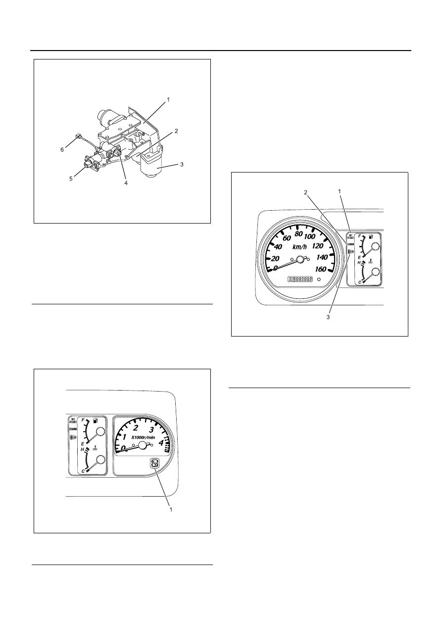
Legend
1. Gear Position Indicator
N7A2018E
N7A2010E
Legend
1. 1st Gear Start Indicator Lamp
2. Economy Mode Indicator Lamp
3. Transmission Warning Lamp
N7A2011E