Isuzu N-Series. Manual - part 881


  Index      Isuzu     Isuzu N-Series - service repair manual


Search            


Content   ..  879  880  881  882   ..


Isuzu N-Series. Manual - part 881


7B1-48 MANUAL TRANSMISSION (MZZ)
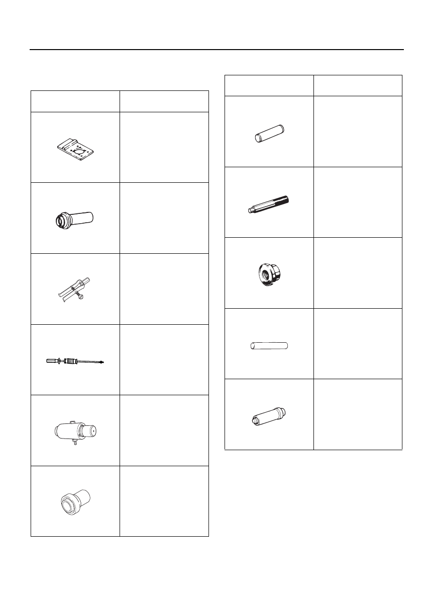
SPECIAL TOOLS

Special Tools

Illustration

Tool Number / 

Description / Remarks

9-8529-2101-0 / Drive 

Pinion Flange Bracket

5-8840-2751-0 / Oil Seal 

Installer

5-8840-0027-0 / Bearing 

Remover

5-8840-0084-0 / Sliding 

Hammer

5-8840-2755-0 / Bush 

Remover & Installer

5-8840-2558-0 / Oil Seal 

Installer

9852921010

5884027510

5884000270

5884000840

5884027550

5884025580

5-8840-2244-0 / Bearing 

Installer

5-8840-0007-0 / Driver 

Handle

5-8840-2753-0 / Bearing 

Installer

5-8840-2345-0 / Clutch 

Hub & Collar Installer

5-8840-2245-0 / Oil Seal 

Installer

Illustration

Tool Number / 

Description / Remarks

5884022440

5884000070

5884027530

5884023450

5884022450

7C-2 CLUTCH (FOR MZZ TRANSMISSION)

DESCRIPTION

Clutch System

Notice:
When fasteners are removed, always reinstall them at
the same location from which they were removed. If a
fastener needs to be replaced, use the correct part num-
ber fastener for that application. If the correct part num-
ber fastener is not available, a fastener of equal size and
strength (or stronger) may be used. Fasteners that are
not reused, and those requiring thread locking com-
pound will be called out. The correct torque value must
be used when installing fasteners that require it. If the
above conditions are not followed, parts or system dam-
age could result.

Driving Members

The driving members of a clutch usually consist of two
flat surfaces machined to a smooth finish.
One of these surfaces is usually the rear face of the en-
gine flywheel, and the other is a comparatively heavy flat
ring with one side machined. This part is known as the
pressure plate. It is fitted into a steel cover, which also
contains some of the operating members, and is bolted
to the flywheel.

Driven Member

The driven member is a clutch disc with a splined hub
which is free to slide lengthwise along the splines of the
clutch shaft, but which drives the shaft through these
same splines. Suitable frictional facings are attached to
each side of the clutch disc by means of rivets. These
facings must be heat resistant since friction produces
heat.

Operating Members

The driving and driven members are held in contact by
spring pressure.
The throwout (clutch release) bearing is a ballthrust
bearing contained in the clutch housing, mounted on a
sleeve attached to the front of the transmission case.
The throwout bearing is moved by the clutch release
yoke to contact the release levers and move the pres-
sure plate to the rear, thus separating the clutch driving
members from the driven member when the clutch pedal
is depressed by the driver.

Clutch Controls

This system utilizes hydraulic pressure as a means of
transmitting clutch pedal movement to the clutch re-
lease mechanism. The system consists of a pedal-oper-
ated master cylinder and a slave cylinder,
interconnected with hydraulic lines. The clutch pedal is
connected to the master cylinder push rod, and the
slave cylinder push rod is connected to the clutch re-
lease fork.

CLUTCH (FOR MZZ TRANSMISSION) 7C-3

DIAGNOSIS OF CLUTCH

PROBLEM

POSSIBLE CAUSE

CORRECTION

Clutch Slips

1. Binding of release levers in the 

pressure plate and cover assembly.

1. Replace the clutch cover assembly.

2. Clutch release levers improperly 

adjusted.

2. If levers are in place, adjust free pedal.

3. Facings loose on the clutch disc.

3. Replace the driven disc assembly.

4. Improper clutch release bearing ad-

justment.

4. Adjust for proper clearance (free pedal).

5. Binding or sticking clutch pedal as-

sembly.

5. Repair or replace faulty parts.

Check linkage for proper adjustment.

6. Weak or broken clutch pressure 

springs.

6. Replace the clutch cover assembly.

7. Burned clutch facings.

7. Replace clutch driven disc assembly 

and check flywheel and pressure plate 
friction surfaces for damage replace 
parts as necessary.

8. Binding or sticking of the clutch disc 

hub on the transmission drive gear.

8. Lubricate splines with high temperature 

grease (if dry). Replace driven discs if 
splined hubs are worn.

9. Release bearing binding on bearing 

retainer.

9. Replace release bearing or lubricate.

10. Warped pressure plate or engine 

flywheel.

10. Replace defective parts. Check trans-

mission, clutch, and engine alignment.

11. No free pedal.

11. Adjust for free pedal, check clutch driven 

disc wear and replace parts as required.

Clutch Chatters During 
Engagement

1. Loose engine mounts.

1. Tighten engine mount bolts to specifica-

tions.

2. Grease or oil on facings.

2. Replace driven disc assembly and repair 

oil leak.

3. Slight binding in linkage during en-

gagement.

3. Check linkage for wear or damage. Re-

place parts as required.

4. Weak pressure springs.

4. Replace clutch cover assembly.

5. Clutch release levers binding during 

engagement.

5. Repair or replace clutch cover assem-

bly.

6. Worn or broken pilot bearing.

6. Replace and lubricate pilot bearing.

7. Rough engine idle.

7. Tune engine to manufacturer's specifi-

cations.

8. Bent or out of plane pressure plate 

fingers.

8. Replace clutch cover assembly if re-

lease fingers are more than 2 mm (0.079 
in) out of plane.

9. Driven disc warped, cracked, or 

loose friction material.

9. Replace driven disc assembly.

10. Pressure plate warped or hot spots. 10. Replace pressure plate or clutch cover 

assembly.

11. Flywheel warpage or discoloration.

11. Replace flywheel.

12. Flywheel housing bore and face not 

aligned.

12. Correct per alignment procedure.


Content   ..  879  880  881  882   ..