Isuzu N-Series. Manual - part 847


  Index      Isuzu     Isuzu N-Series - service repair manual


Search            


Content   ..  845  846  847  848   ..


Isuzu N-Series. Manual - part 847


MANUAL TRANSMISSION 7B-49

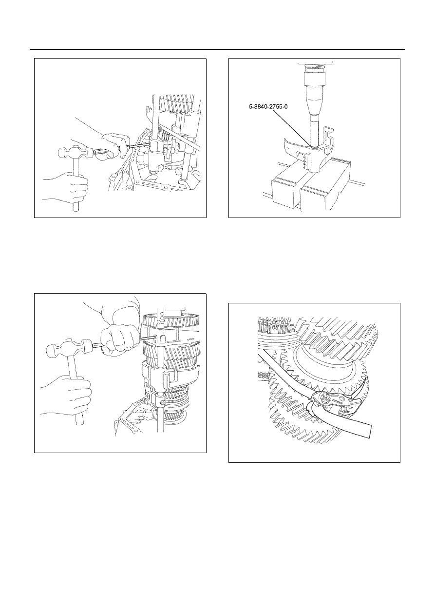
33. Remove the 1st-reverse and 2nd-3rd shift rod, the

1st-reverse shift arm, the 3rd-2nd shift arm, the
1st-reverse and 6th shift block.

• When driving out the spring pin, put a round

pole on the opposite side of the shift rod not to
damage other parts, and then remove the
spring pin using the spring pin remover.

34. Remove the bush from the 4th-5th shift arm using

the remover 5-8840-2755-0.

35. Remove the bush from the 1st-reverse shift arm

using the remover 5-8840-2755-0.

36. Remove the bush from the 3rd-2nd shift arm using

the remover 5-8840-2755-0.

• Use a round pole whose length is enough to

push the remover to the end.

37. Remove the magnet from the clutch housing.
38. Remove the mail shaft assembly, the top gear

shaft assembly and the counter shaft assembly.
a. Tie the main shaft assembly, the counter shaft

assembly and the top gear shaft assembly at
the two positions not to let them come apart us-
ing a lashing belt or other belts with a fixing
function, and then fix them securely.

b. Install the bearing remover to the main shaft

and secure it with a lock nut, hang them with a
hoist and a wire, and then remove the top gear
shaft assembly, the main shaft assembly, the
counter shaft assembly from the clutch housing
as a unit while spreading the top gear shaft
bearing outer snap ring installed to the clutch
housing.

N7A1147E

N7A01148E

N7A1094E

N7A1095E

7B-50 MANUAL TRANSMISSION

39. Check the clutch housing bush, and then remove it

from the clutch housing using a pliers if it is worn or
damaged.

40. Check the front oil seal, and then remove it from

the clutch housing using a flat-tip screwdriver if it is
worn or damaged.
Check each part, and then correct and replace it if
some worn, damaged or faulty parts are found.

41. Check each part of the shift mechanism, and then

correct light damage, deflection or stepped wear.
Replace it when it is heavily damaged or its usage
limit is over.

• Deflection, wear and damage of the shift rod

and the shift arm

• Shift arm thickness

– Measure the thickness of the shift arm tip us-

ing the micrometer.

42. Check whether the speedometer driven gear and

the driven gear bush are worn.

• Replace them if they are worn heavily.

N7A1096E

N7A1097E

N7A1098E

Shift arm thickness, mm (in)

Standard

Limit

1st-reverse

3rd-2nd

5th-4th

9.60 — 9.85

(0.378 — 0.387)

9.0

(0.354)

6th

9.60 — 9.85

(0.378 — 0.387)

9.3

(0.366)

N7A1100E

MANUAL TRANSMISSION 7B-51

43. Measure the clearance between the insert and the

block ring groove.

• Measure the clearance using a caliper.
• Replace the insert and the block ring if their

measured values are out of the limit.

Assembly

1. When finding the oil seal worn and damaged after

the check and replacing it with a new one, apply
engine oil 5W-30 around the oil seal, and then
press in the oil seal into the clutch housing using
the installer 5-8840-2558-0.

• Apply Besco L2 grease on the oil seal lip por-

tion.

Caution:
Be careful not to damage the oil seal lip portion.

2. When the clutch housing bush is replaced with a

new one after checking it for wear and damage,
press it in using the installer 5-8840-2755-0.

• During installation, the direction of the bush

and the position of the caulking should be set
as indicated in the figure.

• For the bush pressing in for the second time

and onwards, press in the bush facing its
notched portion to the clutch housing.

3. Install the main shaft assembly, the top gear shaft

assembly and the counter shaft assembly.
a. Tie the main shaft assembly, the counter shaft

assembly and the top gear shaft assembly at
the two positions not to let them come apart us-
ing a lashing belt or other belts with a fixing
function, and then fix them securely. Be careful
not to drop the top gear shaft while lifting up.

Clearance between insert and block ring, mm (in)

Standard

6th

3.46 — 3.76 (0.136 — 0.148)

N7A1101E

N7A0326E

N7A1104E

N7A1105E

7B-52 MANUAL TRANSMISSION

b. Stick up the three of the top gear shaft assem-

bly, the main gear shaft assembly and the
counter shaft assembly on the support stand as
the top gear shaft assembly is put on the top.

c. Install the oil seal protector 5-8840-2793-0 to

the main shaft.

d. Set the top gear shaft bearing outer snap ring

to the clutch housing, spread it using a snap
ring pliers, and then insert it to the clutch hous-
ing after aligning the top gear shaft, the counter
shaft and the shift rod positions.

Caution:

• Make sure the snap ring is installed securely.
• Work carefully not to damage the front oil seal.

4. Install the magnet to the clutch housing.
5. When replacing the 3rd-2nd shift arm bush with a

new one after checking it for wear or damage,
press in the bush using the installer 5-8840-2755-
0.

6. When replacing the 4th-5th shift arm bush with a

new one after checking it for wear or damage,
press in the bush using the installer 5-8840-2755-
0.

7. When replacing the 4th-5th shift arm bush with a

new one after checking it for wear or damage,
press in the bush using the installer 5-8840-2755-
0.

• Press it in taking care of the direction and angle

of the shift arm bush, and then caulk the three
portions except the bush cut and older caulking
portions.

N7A1095E

N7A0329E

N7A0322E

N7A1109E


Content   ..  845  846  847  848   ..