Isuzu N-Series. Manual - part 848


  Index      Isuzu     Isuzu N-Series - service repair manual


Search            


Content   ..  846  847  848  849   ..


Isuzu N-Series. Manual - part 848


MANUAL TRANSMISSION 7B-53

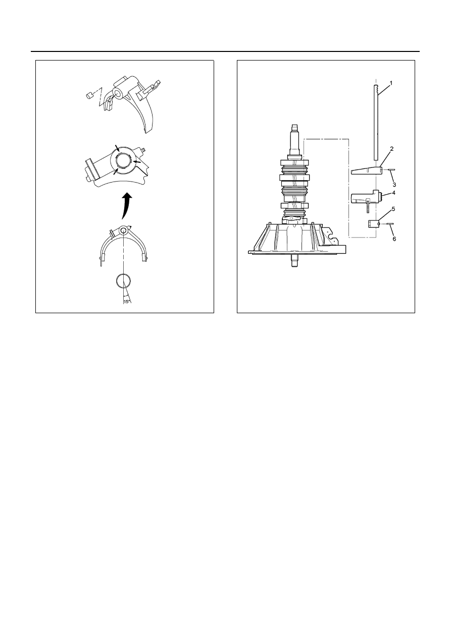
8. Install the 1st-reverse and 2nd-3rd shift rod (1) to

the 1st-reverse and 6th shift block (5), the 2nd-3rd
shift arm (4), the 1st-reverse shift arm (2).

• Drive in the spring pin (3) and (6) using a ham-

mer after aligning the spring pin hole.

• When pressing in the spring pin, put a round

pole on the opposite side of the shift rod not to
damage other parts, and then press in the
spring pin.

9. Install the 4th-5th and 6th shift rod (1) to the 4th-5th

shift arm (3), 1st-reverse and 6th shift block (2).

• Drive in the spring pin (4) using a hammer after

aligning the spring pin hole.

• When pressing in the spring pin, put a round

pole on the opposite side of the shift rod not to
damage other parts, and then press in the
spring pin.

N7A0332E

N7A0339E

7B-54 MANUAL TRANSMISSION

10. Apply ThreeBond 1215 to the mating surface of the

transmission case and the clutch housing, and
then install the clutch housing.

• Wipe off moisture and lubricant from the mating

surface, and then apply the gasket continuous-
ly with a diameter of 2 mm (0.079 in) or more.

Tighten:
Clutch housing to 46 N

⋅m (4.7 kg⋅m / 34 lb⋅ft)

11. Install the bearing rear outer race to the transmis-

sion case.

12. Install the spring pin; 4th-5th and 6th shift rod.

Caution:
When the snap ring is deformed or damaged, replace it
with a new one, and make sure it is completely installed.

13. Install the shim to the counter shaft rear bearing.

a. Shift the position to the neutral.
b. Set the transmission assembly with the clutch

housing faced down.

4

2

3

1

N7A0570E

N7A1113E

N7A0353E

MANUAL TRANSMISSION 7B-55

c. Revolve the counter shaft more then 30 times

and smooth the taper roller bearing.

d. Select the counter shim.

• Measure the depth at the points equally divided

into three from the end surface of the transmis-
sion case to the outer ring edge surface of the
counter shaft rear bearing, and then take an av-
erage of them.

• Select the shim whose thickness agrees with

the list below.

14. Install the snap ring to the main shaft rear bearing. 
15. Apply engine oil 5W-30 to the needle bearing, in-

stall the reverse idle gear and needle bearing, and
then insert the reverse idle shaft.

• The arrow mark shows the direction of the

transmission front side.

16. Install the retainer to the transmission case.

Tighten:
Retainer to 26 N

⋅m (2.7 kg⋅m / 19 lb⋅ft)

Caution:
Clean up the sealing agent on the screw thread of the
transmission case and replace all screws with new
ones.

17. Install the collar and the speedometer gear.
18. Assemble the 6th clutch hub assembly (2) and the

sleeve (1) following the procedure below.
a. Assemble the insert (3) securely to the block

ring insert groove.

b. Install the insert spring (4) to the insert.

Measured value, mm (in)

Thickness of 

applicable shim

more than — less than

3.34 — 3.40 (0.132 — 0.133)

3.19 (0.125)

3.28 — 3.34 (0.130 — 0.131)

3.13 (0.123)

3.22 — 3.28 (0.127 — 0.129)

3.70 (0.120)

3.16 — 3.22 (0.125 — 0.126)

3.01 (0.118)

3.10 — 3.16 (0.122 — 0.124)

2.95 (0.116)

3.04 — 3.10 (0.120 — 0.122)

2.89 (0.113)

2.98 — 3.04 (0.118 — 0.119)

2.83 (0.111)

2.92 — 2.98 (0.115 — 0.117)

2.77 (0.109)

2.86 — 2.92 (0.113 — 0.114)

2.71 (0.106)

2.80 — 2.86 (0.110 — 0.112)

2.65 (0.104)

2.74 — 2.80 (0.108 — 0.110)

2.59 (0.101)

2.68 — 2.74 (0.106 — 0.107)

2.53 (0.099)

2.62 — 2.68 (0.104 — 0.105)

2.47 (0.097)

2.56 — 2.62 (0.101 — 0.103)

2.41 (0.094)

2.50 — 2.56 (0.099 — 0.100)

2.35 (0.092)

2.44 — 2.50 (0.096 — 0.098)

2.29 (0.090)

2.38 — 2.44 (0.094 — 0.096)

2.23 (0.087)

2.32 — 2.38 (0.092 — 0.093)

2.17 (0.085)

2.26 — 2.32 (0.089 — 0.091)

2.11 (0.083)

N7A1115E

N7A0338E

N7A1090E

7B-56 MANUAL TRANSMISSION

Caution:

• When assembling the insert spring, equalize the

length of the both edges of the spring not to ad-
versely interfere with the inside diameter of the
hub.

• Make sure that the open part of the insert spring

assembled on the reverse side, is not aligned with
the open part of the front side.

c. Make sure the clutch hub (5) and the sleeve (6)

slide smoothly.

d. Install a new stopper plate to the clutch hub.

19. Apply engine oil 5W-30 to the needle bearing and

the block ring bore, assemble the 6th gear, the
needle bearing and the 6th block ring, align the as-
pect of the clutch hub block ring groove, assemble
the 6th clutch hub assembly and the sleeve, and
then press in them using the installer 5-8840-2244-
0 and a hammer.

N7A1172E

N7A1173E

N7A1174E

N7A1175E


Content   ..  846  847  848  849   ..