Isuzu N-Series. Manual - part 617


  Index      Isuzu     Isuzu N-Series - service repair manual


Search            


Content   ..  615  616  617  618   ..


Isuzu N-Series. Manual - part 617


6C-38 ENGINE FUEL

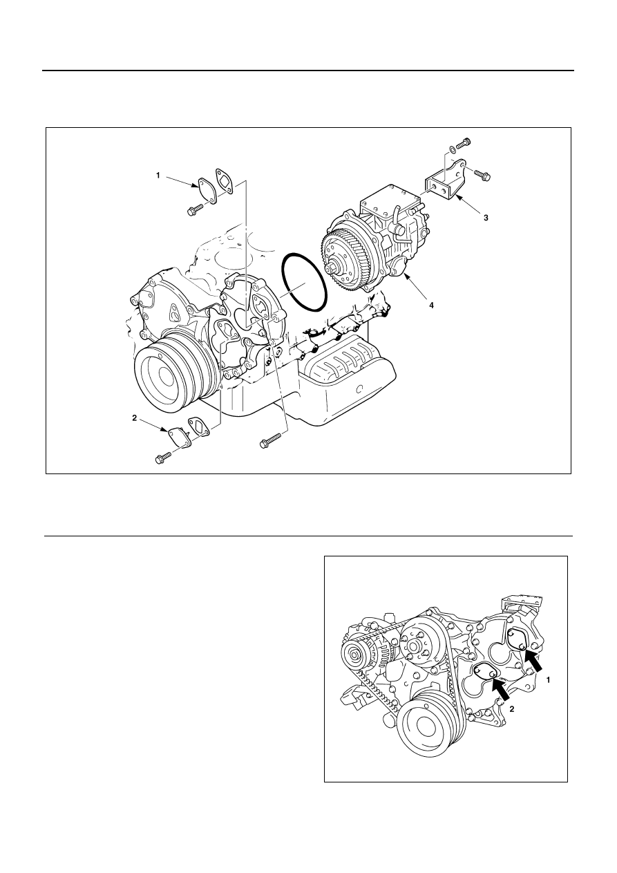
INJECTION PUMP ASSEMBLY (4JH1-TC)

Component

Removal

Preparation:
Remove the fuel pipe and the injection pipe.

1. Check Hole Cover: Injection Pump Gear

Remove the check hole cover (1).

2. Check Hole Cover: Scissor Gear

• Remove the check hole cover (2).
• Rotate the crank pulley until the hole used to fix the

scissor gear (the hole extends from the check hole
cover) becomes visible.

• Thread the lock bolt into the hole in the scissor

gear.

Legend

1. Check hole cover: Injection pump gear

3. Injection pump bracket

2. Check hole cover: Scissor gear

4. Injection pump assembly

N6A3448E

N6A3449E

ENGINE FUEL 6C-39

• Rotate the crank pulley to align the dot on the pul-

ley with the crankshaft TDC mark.

• Check that the injection pump mark is aligned with

the arrow mark. If the marks are not aligned, rotate
the crank pulley an additional full turn.

Notice:
When the scissor gear and check hole cover are not in-
stalled, the crank pulley can be turned with the scissor
gear lock bolt in place.

3. Injection Pump Bracket

Remove the bracket fixing bolts at the rear of the
injection pump.

4. Inspection Pump Assembly

Loosen the 6 bolts holding the injection pump as-
sembly.

Notice:
Plug the injection pump delivery holder openings with
the shipping caps (or some similar object) to prevent the
entry of foreign material.

Legend

1. Lock bolt

N6A3450E

N6A3451E

Legend

1. Arrow mark
2. Mark

N6A3452E

N6A3453E

6C-40 ENGINE FUEL

Installation

1. Injection Pump Assembly

• Check the pulley alignment mark and the crank-

shaft TDC mark are aligned.

• Remove the camshaft gear check hole cover to

check camshaft gear mark alignment.

• Install the O-ring.
• Install the injection pump assembly. Maintain injec-

tion pump gear mark and arrow mark alignment
during the installation procedure (look through the
check hole).

• Tighten the injection pump bolts to the specified

torque.

Tighten:
Pump Bolt to 15 N

⋅m (1.5 kg⋅m/11 lb⋅ft)

2. Injection Pump Bracket

• Install the injection pump bracket to the gear of the

injection pump and tighten the bolts to the specified
torque.

Tighten:
Bracket Bolt to 25 N

⋅m (2.5 kg⋅m/18 lb⋅ft)

• Rotate the crank pulley until the scissor gear lock

bolt is visible through the check hole. Remove the
bolt.

Legend

A. Camshaft gear

N6A3451E

N6A3454E

Legend

1. Arrow mark
2. Mark

N6A3452E

N6A3453E

ENGINE FUEL 6C-41

3. Check Hole Cover: Scissor Gear
4. Check Hole Cover: Injection Pump

Caution:
Install the check hole covers.

• Be absolutely sure that the check hole covers are

properly installed.

• Rotate the crank pulley 2 full turns to confirm that

the lock bolt has been removed (if you have forgot-
ten to remove the bolt, the bolt will strike the check
hole guides and the crank pulley will not turn). 

Legend

1. Lock bolt

N6A3450E

N6A3455E


Content   ..  615  616  617  618   ..